Matt's Weekly Shop Update
Kitchen Island, Barn Power – March 2024 Update
Welcome to my shop! This is a quick update to let you know what I’ve been up to. This big chunky thing is the leg
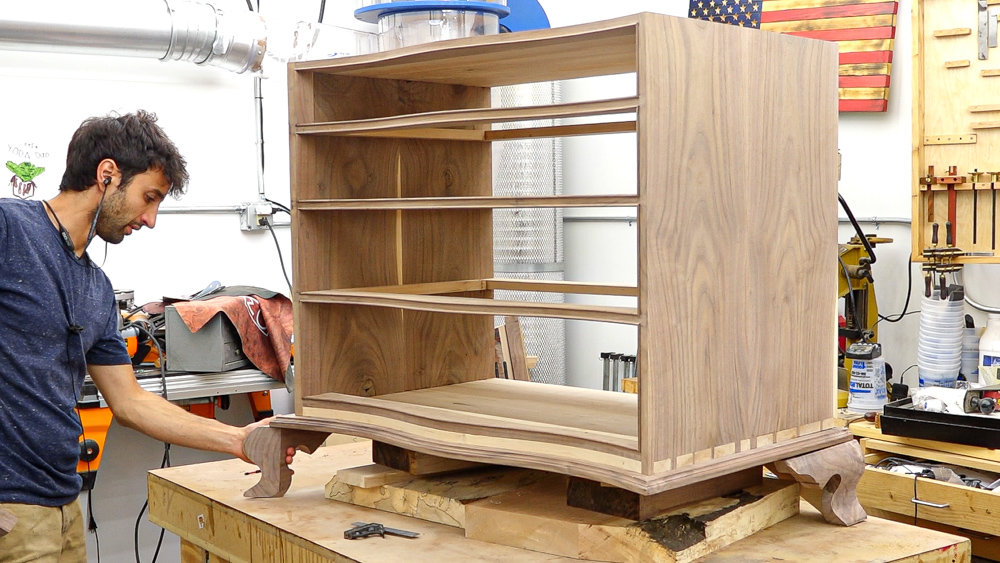
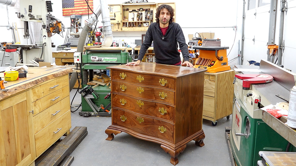
Welcome to my shop, and welcome back to my series on building this serpentine chest of drawers.
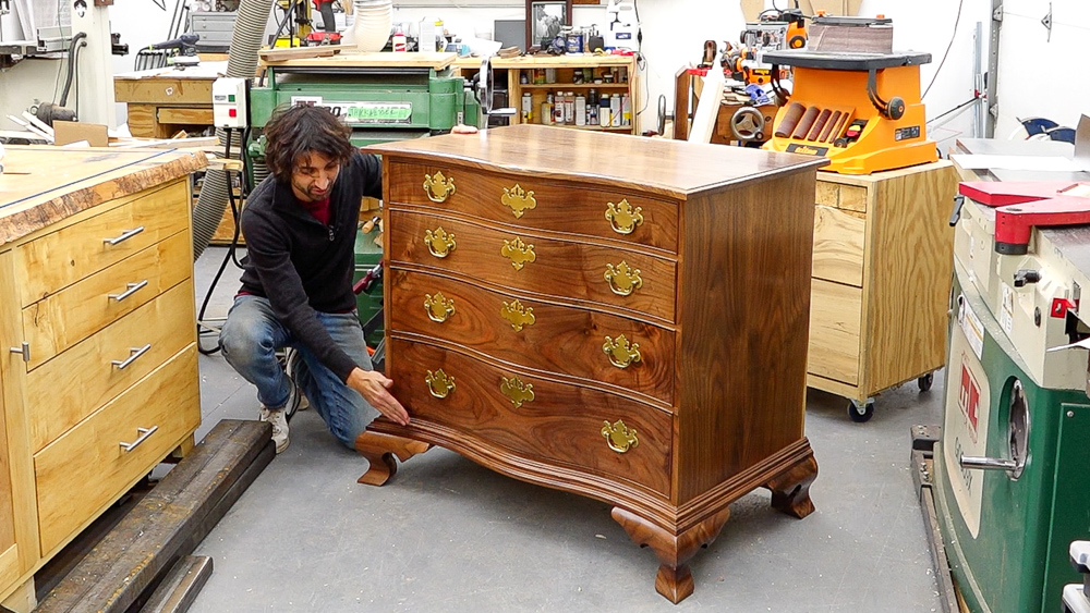
This time, we’re going all the way down here to the bottom. We’re going to make the base, which is serpentine just like the rest of the case. We have a frame. We have ogee bracket feet, with the front ones being curved. And then we have a transition molding here, which also follows that serpentine curve along the front.
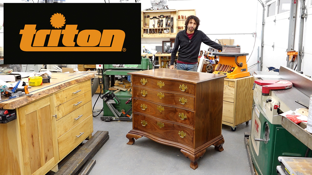
Again, I want to say a big thank you to Triton Tools for sponsoring this series and continuing to support the channel as they have for the last several years. This time, we’re going to be taking a closer look at the Oscillating Spindle and Belt Sander later on.
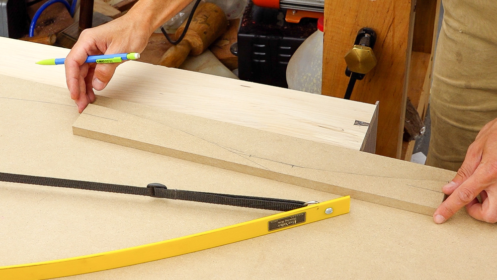
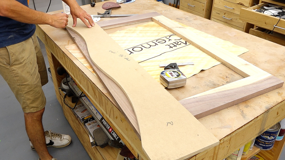
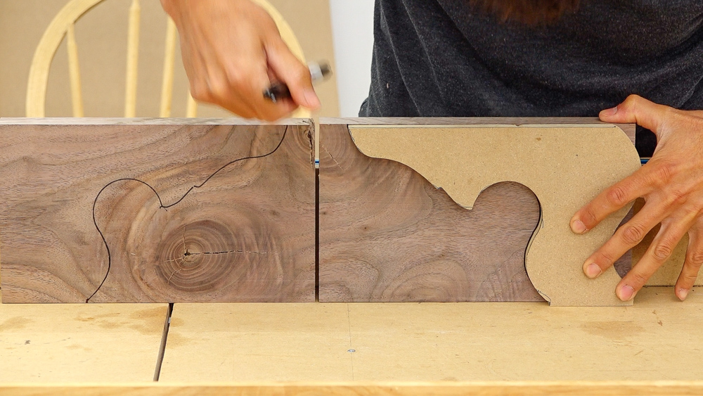
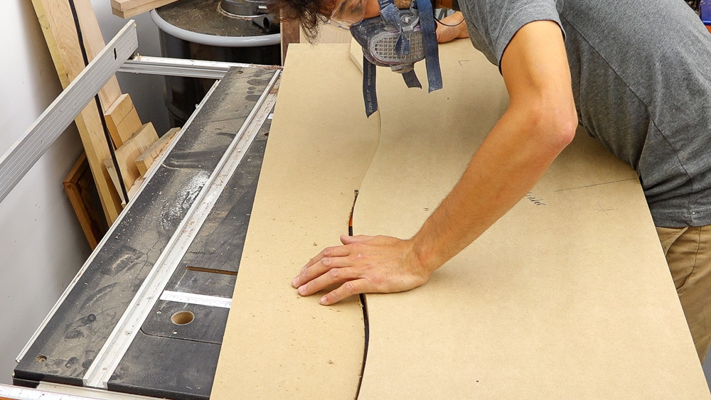
For now we’re going to make some templates. That’s basically all this project is, templates. The first template I need is an exact copy of the bottom of the case. I traced the curve onto the MDF and marked the extents of the case so later I can put it back in the same place for routing after cutting away the waste at the bandsaw.
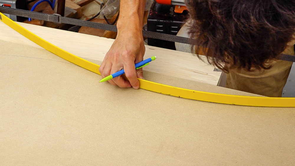
Now I need to extend the curve past where the case ends. I still have my drawing bow set for when I came up with the serpentine curve, so I can use it to extend the line. If you want to make this project a bit easier, extend the curve with a straight line so you’re not trying to miter pieces together along a curve. I think having the curve extend all the way to the extent of the base is just more elegant.
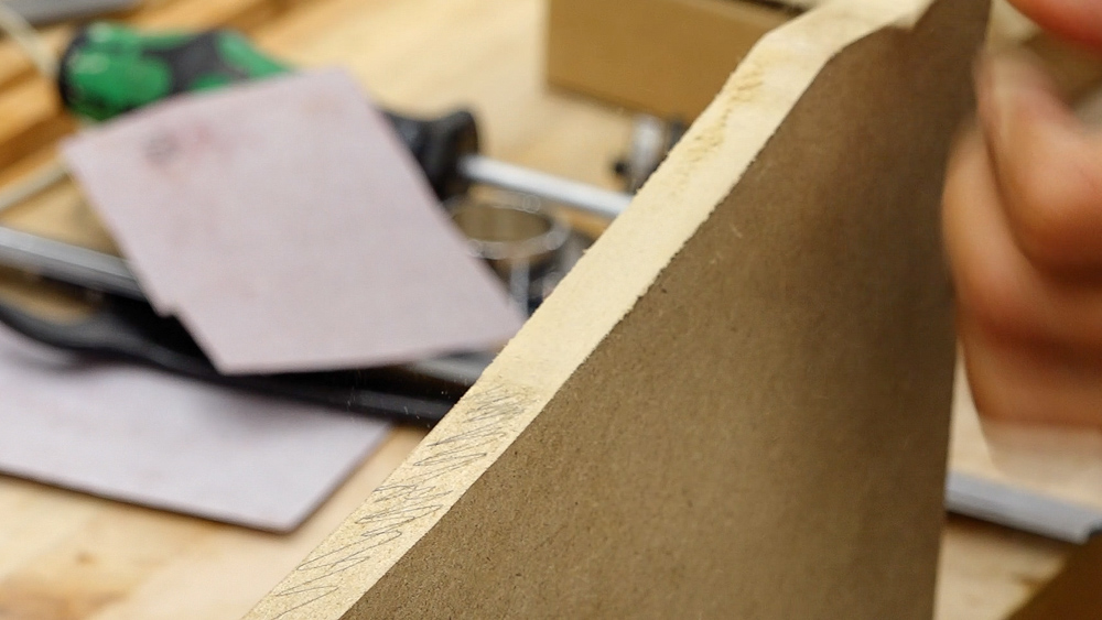
After flush trimming as much as I can, I can start blending a new area into the curve. I added some pencil lines on the flush trimmed area, so I can make sure as I’m working that I’m not touching any of that.
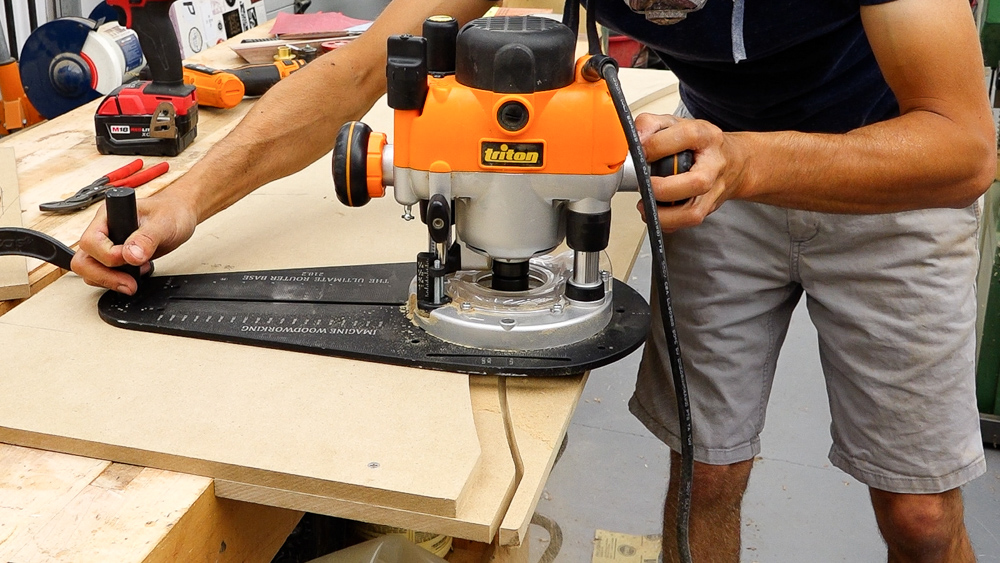
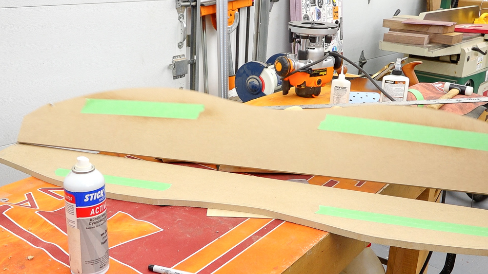
Now this is my master template, and I can start making the offset template, which will become the outside edge of the base. I want the base to be an inch and 1/16 bigger than the case. I don’t have a single bit and bushing combo to get there in one go, so I’ll do it in two. The first pass is done with a 1/4-inch bit, a two-inch bushing, which gives me an offset of 7/8 of an inch. This gives me an intermediate template which is, surprise, 7/8 of an inch offset from the original. The next setup is a 3/8-inch bit with a 3/4 inch bushing giving me an offset of 3/16. This’ll be the final template which we’ll use on the frame, which we will make next.
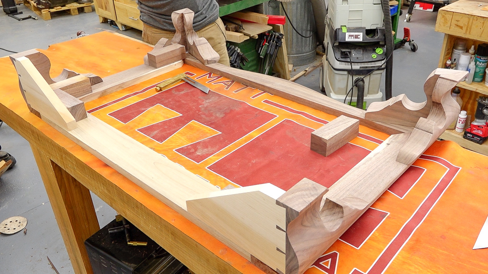
Construction of the frame is pretty simple. The front corners are mitered with the sides running all the way to the back. The sides then get connected with a piece of secondary material in the back.
So we finally have our frame that’s ready to go. I’m going to start getting it shaped and getting it attached to the case. I have my offset template, which I can use on the frame. We’ll get it traced out and get the waste cut away at the bandsaw. Then we’ll get this template stuck down to the frame and route the actual profile to get that curvature.
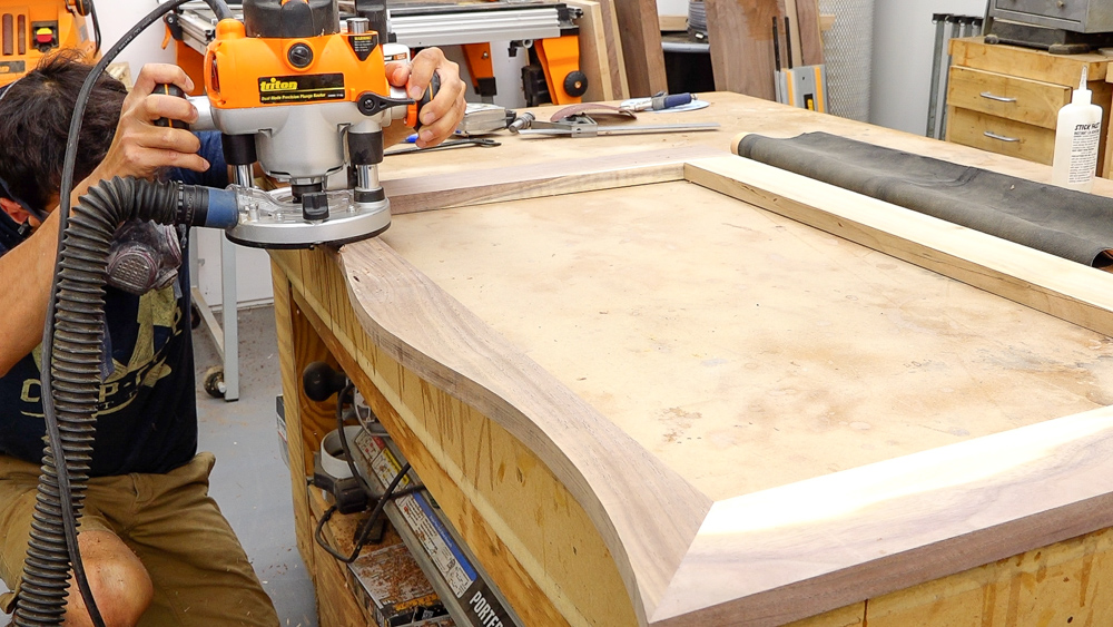
And then from there, we can go ahead and add the edge profiling. So on the bottom side, that’s the easy one, just a quick round over. And then on the top we have the classical profile. So we’ll go ahead and make that one go around the perimeter as well. The only little fun little trick here is on the backside of the frame. We’ll add a little bit of a waste block, that way we don’t have to worry about going around the corner and cutting in deeper on the back corner of that frame. We can go all the way past it, remove that block. We won’t have to worry about messing up that back corner.
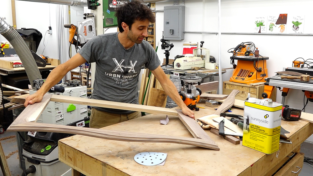
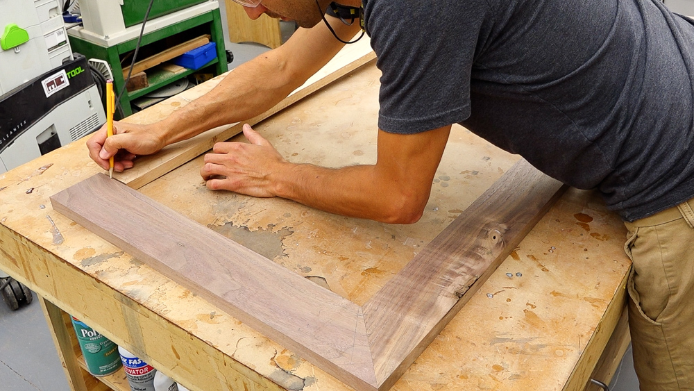
Here is the completed transition frame. And I have to tell you, this is actually my third attempt at making this component. The first one I made with the sides a 1/4-inch too short, so it was a little too small for the case. I just cut the sides off and kept the front and made new sides. The issue with that was that I second guessed myself when I went into this. I had originally figured I need to create the angles on here at the miter that the curve creates, not at a 45. I even went through the work of filming how I approximated the angle of the curve at that corner intersection joint, and then how to bisect that with a set of dividers and get the new actual miter angles. But, you know, I second guessed myself and just ignored it. So this is the new final one. It is done. The miter angle here on the side piece is at 54 degrees. And then the miter angle on the front piece is at 36 degrees.
Let’s put it on the case. I’m just going to throw it on the case, get it lined up, and screw it to the underside. I will permanently attach it later, but for now the screws will allow me to remove it as we move forward with things.
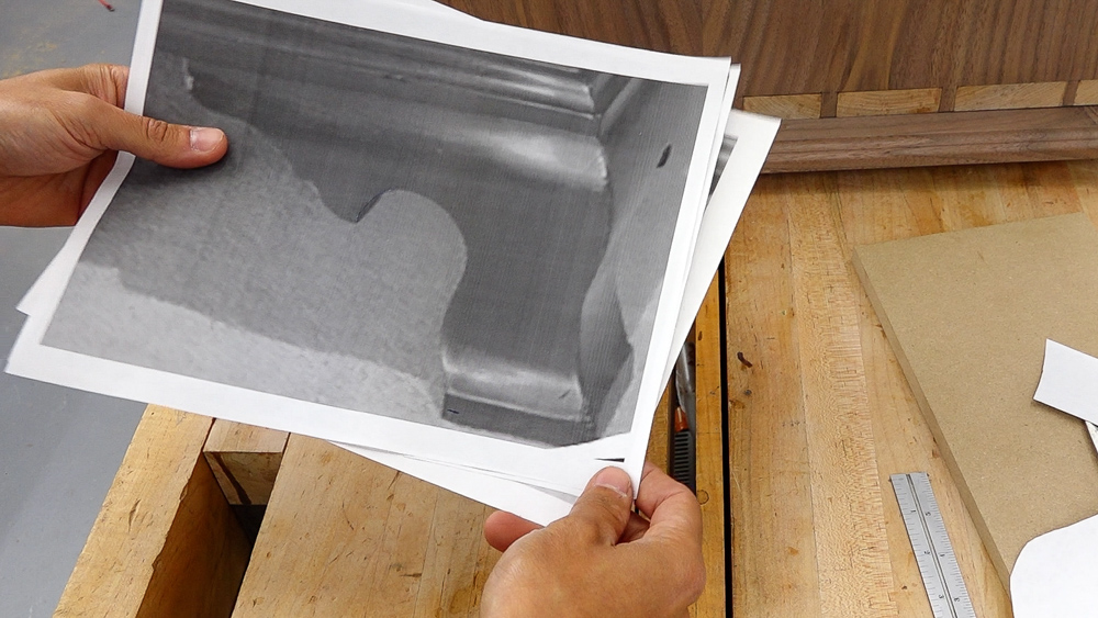
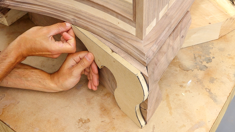
With the transition frame out of the way, next we’re going to start working on the ogee bracket feet, which will go underneath the frame and support the whole case. So here’s the setup for you. I went back to the original picture, and I got some zoomed in pictures to guide my process as I create these feet. I’m not trying to duplicate this piece perfectly, but this should give me a good starting point. This is the front right corner of the piece, and I have manipulated this image to flatten it and to fix the distortion based on the curvature of the case.
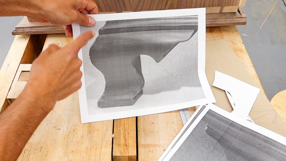
Now on the left side of the case, that picture gave us a really good profile view of the front curve. So this is the curve I’m going to use for the front of the foot, and I’m going to combine that with this ornamentation part on the upper part of the foot from the right side of the case.
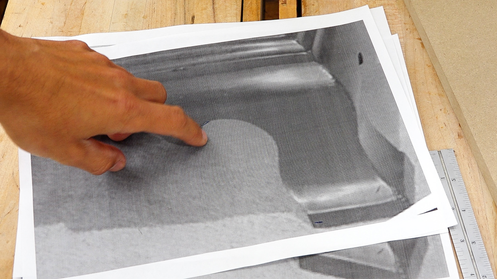
So this first area here I’ll be doing as a circle segment. This will be drilled with a drill bit, and then the curves will come off of that. The other thing I want to do is I’m going to shorten up the bottom area. I don’t like this heavy foot area, so I’m going to probably take that down to about half the height.
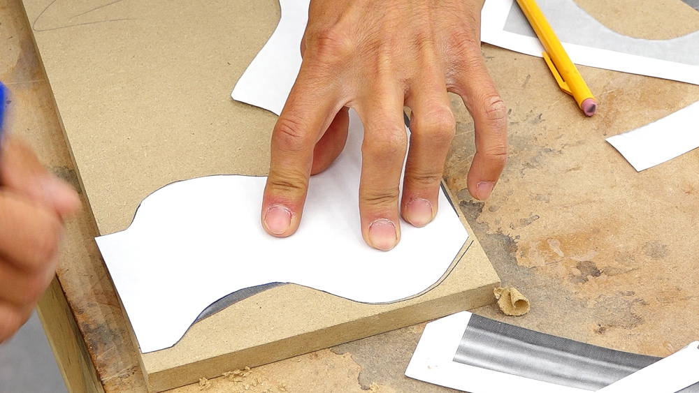
So I have some scissors and some MDF. We’re going to make a first version template, and then we can always tweak things from there. The nice thing about making templates and working with MDF is that it’s pretty easy to change the shape and start over.
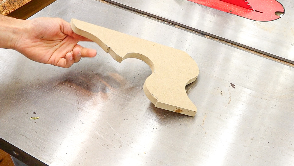
Somewhat surprisingly, I’m actually really happy with this first iteration of this leg. I’m going to move forward with this as my template.
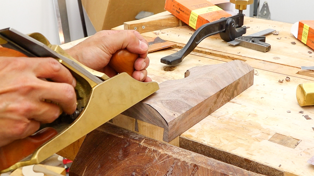
With my stock all prepped, now I’m ready to start working on the ogee profile section. I’ve transferred the profile from the foot onto the end of the board so I have something to start with.
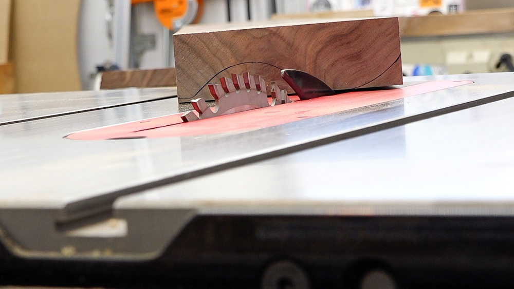
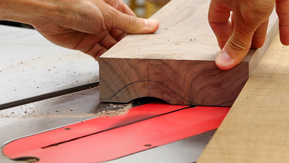
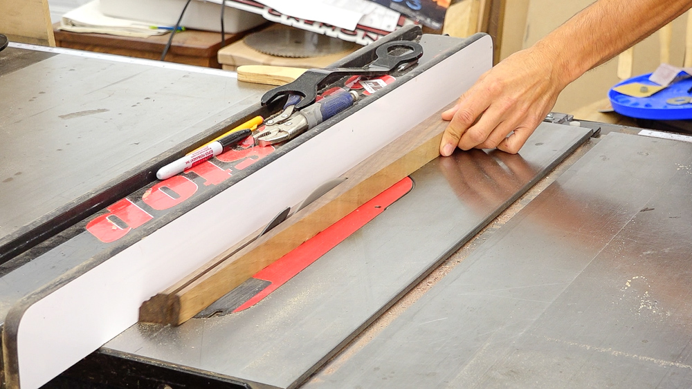
I’m going to do the big cove first, and I’m doing it here at the table saw by running the board diagonally across the blade. It makes an absolute mess, but it works really well. The setup for this is not super precise because we’re doing a lot of eyeballing. Basically you lay your board on a table and you just get it in a rough position. Then you sight down across the table, past the blade and look at your cut line on the board and envision the blade removing that material.
Once you’ve figured out the position left to right and the angle that the workpiece needs to be at, you can attach a fence to your table, and that’s going to be what we’re going to guide the board across. You have a few variables you can play with: the angle of the fence, the position of the fence, and the angle of the blade. If you have a perfectly symmetrical curve, that blade’s going to be at 90. If you want a little bit of an asymmetrical curve, like I have here, then you have the blade tilted, and you can make an asymmetrical curve. The nice thing about this is we have a lot of material to remove. We’re going to be raising the blade very slowly so we can make adjustments as we go. If it looks like the curve we’re creating is a little bit off, we can make an adjustment. I’m going to raise a blade about 1/16 of an inch at a time, run the board across there until we get down to the line.
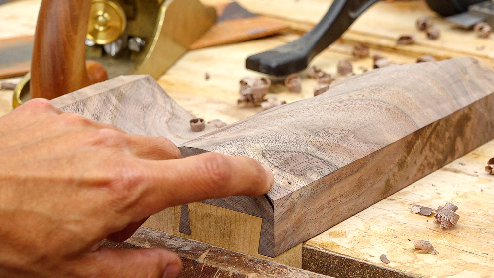
I’m going to make a few passes and see where things end up. If we need to make any adjustments along the way, we will do that as we go.
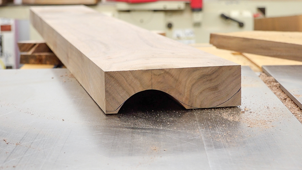
That made a mess, but you can see that we are pretty close. The curve is pretty well dialed in, we just have a little bit of material left to knock out, which I will do next.
These little areas are just going to be with the fence and a saw blade just moving the fence and tipping the blade to remove as much of that waste as possible. We’ll have a little bit of blending and cleanup work to do once these feet are actually made, but the machines take care of the bulk of the shaping work at this step.
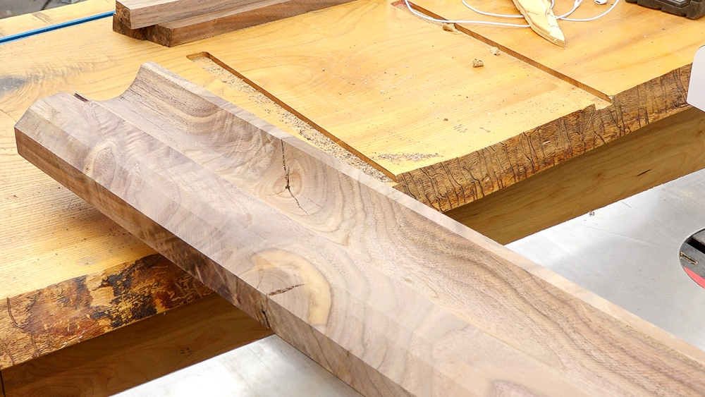
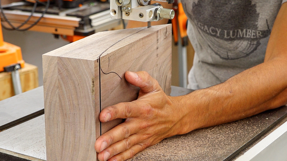
Okay, so there is our stock ready to rock and roll. We’ll do some more final shaping later on. I’m going to start by making the rear feet since they are the easiest. So I’m going to pull the two rear feet from this area on the left side, which will have this cool crotchy figure. The other two front side legs will be more of a straight grain, which will end up matching what I’ll probably end up doing for the front of the case.
![]()
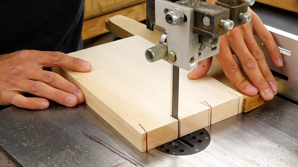
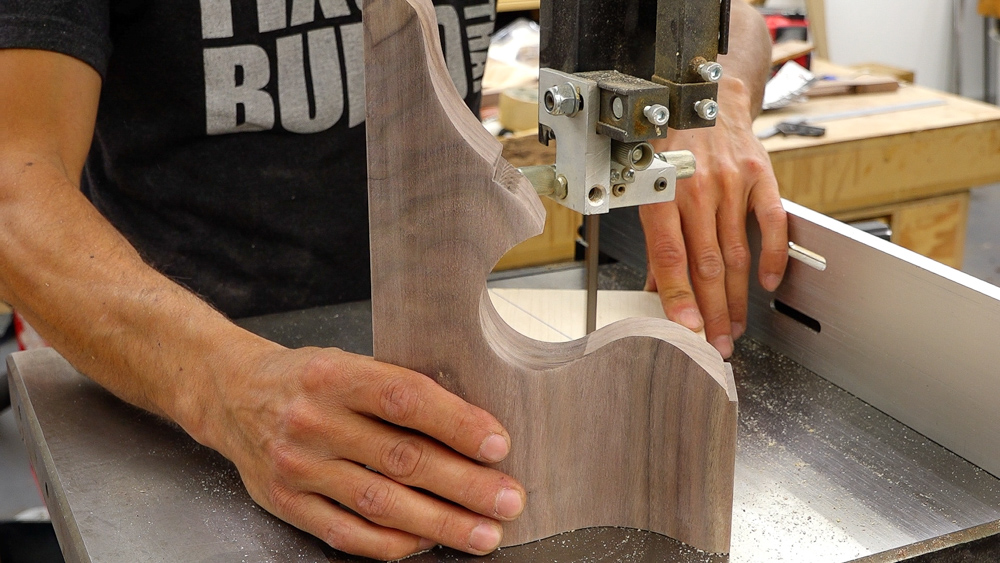
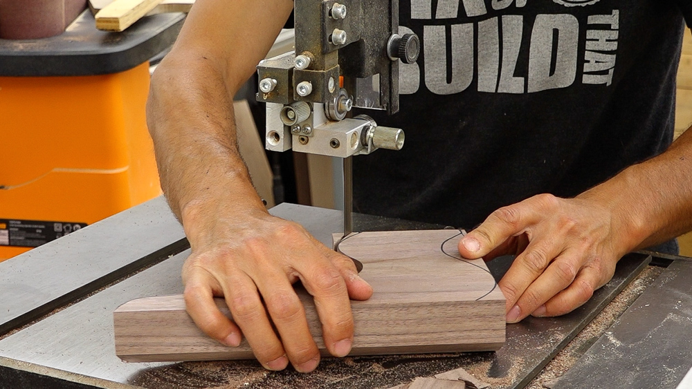
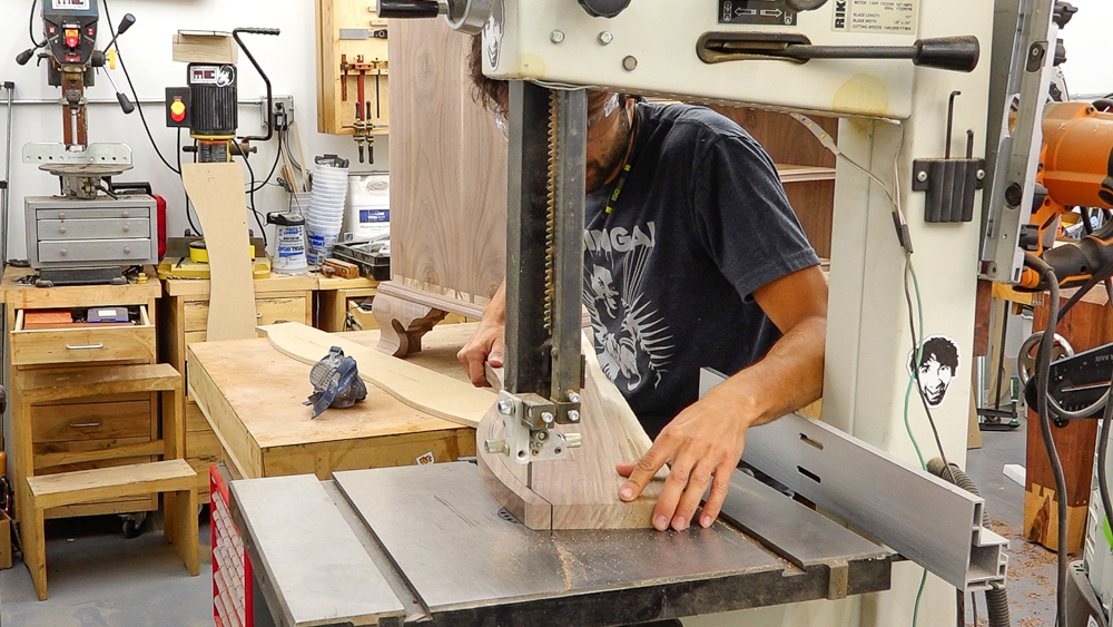
So I’m just going to go ahead and just start cutting these things out. First I blocked off a couple of chunks here, and then the pattern gets laid out from the backside.
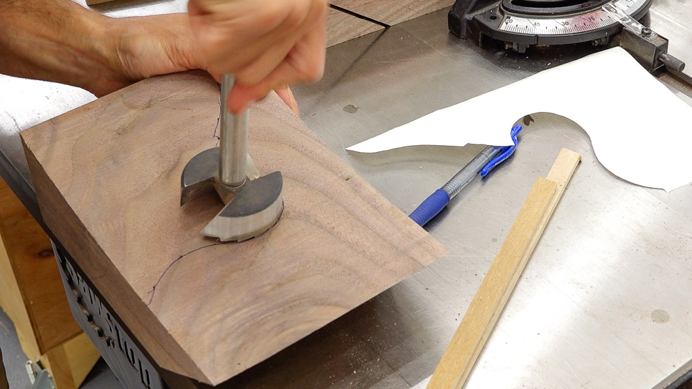
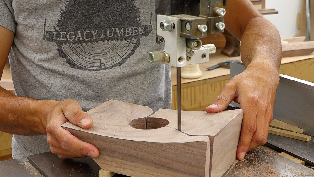
We’ll drill the through hole and cut the profile out. The rear feet, again, do not get the S curve, so this is going to be a simple square cut. We’ll end up just doing a little bit of dovetail work to create a little bracket for the back.
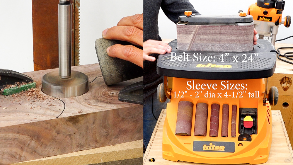
As we’re cutting out the profile on those feet, let’s take a closer look at Triton’s Oscillating Belt and Spindle Sander. A combination machine like this is great, because it allows you a lot of flexibility in just one machine. So you’re able to do concave curves with the individual spindles. And with the belts, you’re able to do convex curves as well as flat work. The spindles go from two inch down the half inch, and they’re all stored nicely on the front of the machine. If you’d happen to need a bigger size spindle, the belt is three inches on one end and an inch and a half on the other end. So you can actually do some spindle sanding-type operations with the belt attachment on here. Swapping the belt to the spindles is actually pretty quick, too. You just have to undo one little fastener, and then the whole assembly slides right off. There is an insert plate that’s stored in the back of the machine that drops on top. You can pick whatever size spindle you want to use, drop the spindle on, and throw on a little washer. Another nice feature is the table does tilt, so if you want to sand something at an odd angle, you can do that as well. So that’s a quick look at Triton’s Oscillating Spindle & Belt Sander, a great tool to have for any kind of curved work.
Next, we’re going to make some dovetails for the rear brackets of those rear feet.
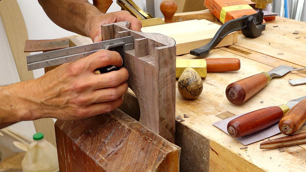
Before I test the fit, I’m just going to make sure that my sockets are good before I go too crazy. I’ll make sure that the bottom and then the back wall is either undercut or square.
Let’s see how we did. It’s a little snug and not quite my best work, but for the back of a case, this works.
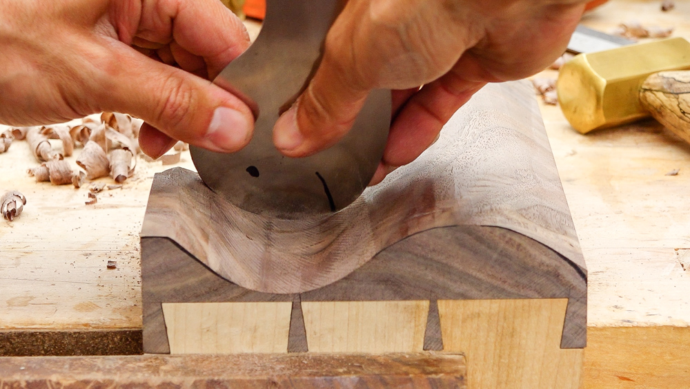
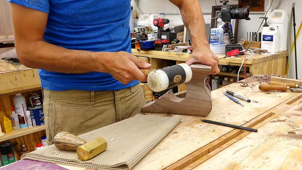
Now I can finalize the shaping of the bracket foot. You want to do all of this convex stuff just with a plane. I’m going to plane all the way from the back to the little peak thing, which is a six inch long segment. So I want to watch my line as I’m working and as I’m doing my stroke I make sure I get all the way through. I’m just arbitrarily tipping the plane to grab the high spots as I’m going. In this case, the line is the waste area, so we want to remove the line.
I think that’s pretty good. I’m going to leave this little corner here. I’m going to have it transition to flat for this much material instead of bringing it back down. I think this curve here is pretty nice the way it is.
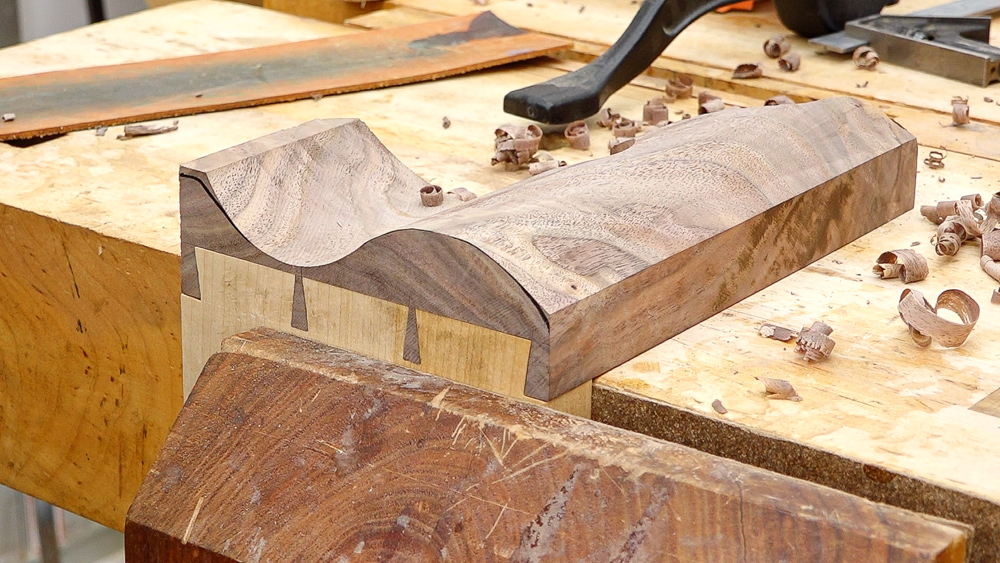
Next, down here. So the bottom of the foot is actually going to stick out less far from the case than the top of the curve. That’s why this shaping is done now, because this is going to get rid of our flat reference. This face is no longer going to be parallel to the underside, which is something we needed when we were doing the drilling and the shaping and profile operation.
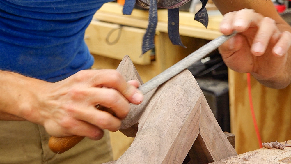
Okay, now I have to clean up the table saw cove area with a gooseneck scraper, and that’s really about it for the rough shaping. Now we’ll do some final finessing, which is just going to be a lot of sanding. I’m going to start at 100 grit and probably work up to 150 for now. That’ll leave me with 180 grit to do later when I’m in the mood.
That takes care of a rear foot. And would you look at that, I have the other side here too. An important thing when making a pair: do not make two of the same. I have made that mistake before. These are pretty much done as far as roughing out goes. They still need all their edges broken and a little bit of finesse work done.
The last little bit on this is going to be to clip the back piece, so I have an angle drawn on here. I’m just going to make that cut, clean it smooth, and then these rear feet will be done, and we can move on to the front feet, which would be far more interesting.
Before I dive into the insanity of the front section of the front feet, I’m going to take care of the sides of the front feet, because those are pretty easy. They’re basically the same as the back ones, with the only difference being that the front is mitered versus being dovetailed. So I’m going to again make a left and right foot using my template. The process for most of this is going to be exactly the same as we did on the back.
I will get the profile transferred and then go through the process of getting the shape cut out. Then I’ll make the mitered cuts, and those miters are going to be at the same angle as the sides of the transition frame. Once that’s taken care of, I can do the final shaping. These are pretty easy and pretty standard. The front part of these feet are going to be a lot more interesting because they are going to be curved, profiled, and shaped.
And that’s one of the side front feet!
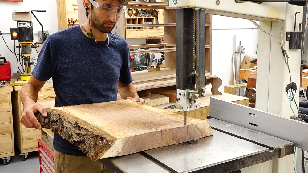
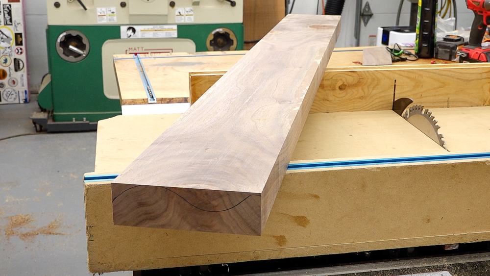
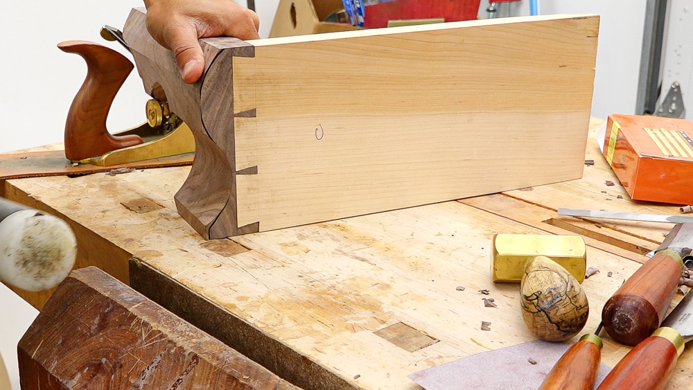
Okay, so let’s make the front feet now. I am going to use a section of this slab for the front feet, which is the same slab I got the other feet out of. This is a separate piece of stock because I needed a lot more thickness to make up those front feet. Before we cut any of the profile in it, we’re going to cut the front of the cabinet into the feet, so this will have a curve in it.
I have my stock here all milled up now, and it is sitting at 2 and 1/32. Now I want to see how much thickness I’m actually going to need to get this curve cut in here, because that’s not going to be thick enough.
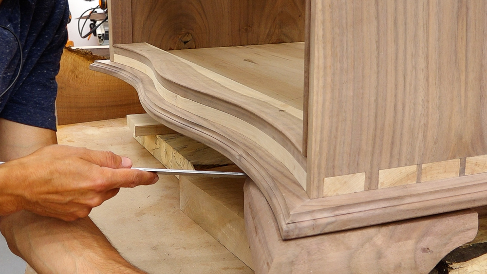
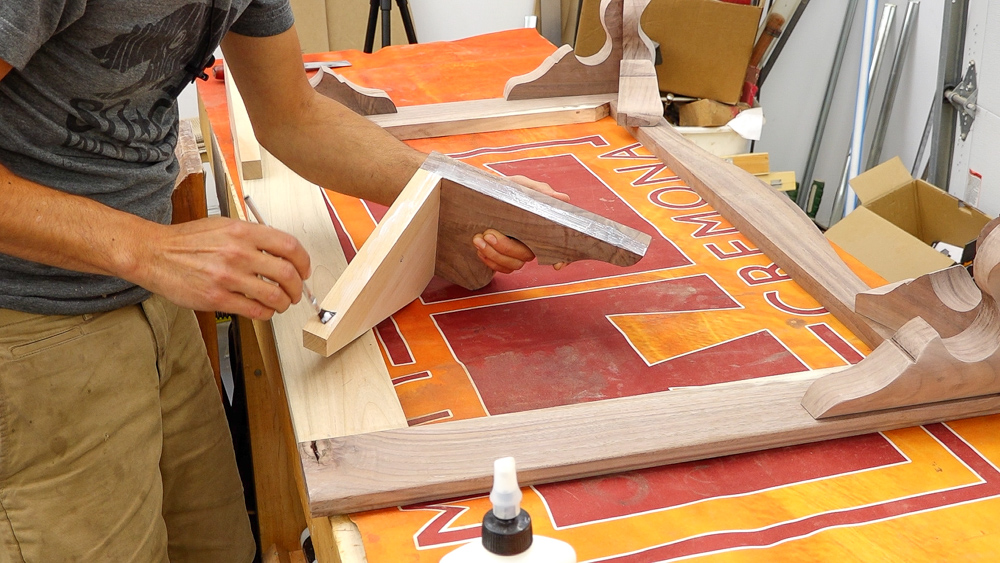
I can take my two feet, put them together, and line up the side foot with the side of the transition frame. Then I can come over to the front foot here and measure how far back it is right now. And it is about 3/4, so I need to add at least that to whatever thickness that the feet are right now. These feet are an inch and 3/4 thick, so I need to make my blank 2 1/2 inches thick.
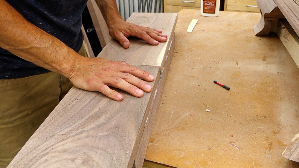
I’m going to add some material to the back face of the front leg stock. That way the material stays the same thickness as we cut that curve out.
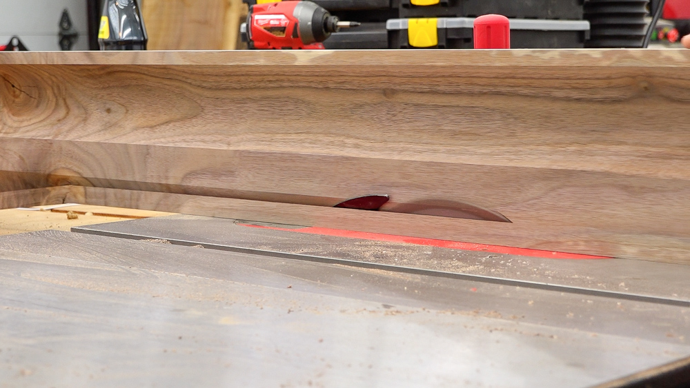
I cut a quick miter cut here on the stock, and I wanted to double check my thickness before I take it down to final thickness. I want to make sure that I have the right amount of material, because if I have too much from the back, I could scoop into the glue seam back here as I’m making the cove, and I don’t want that.
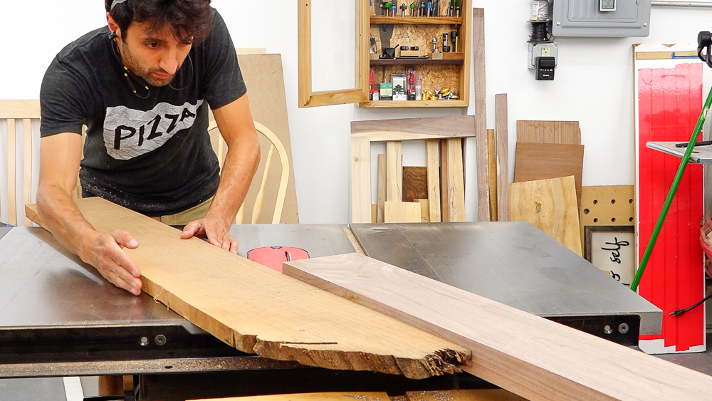
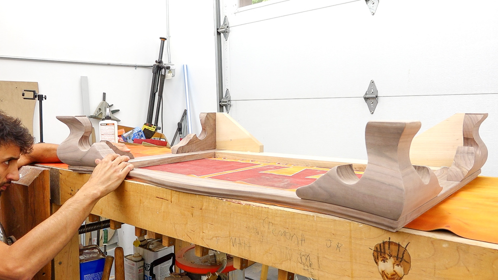
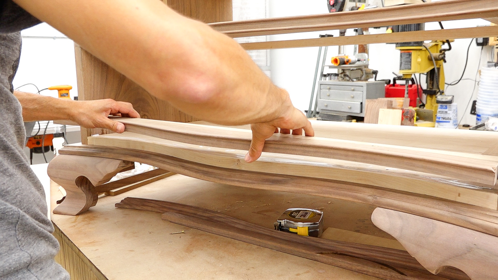
I’m going to set this up like I had it previously and get it aligned. I have my template here to know how much material I’m actually going to need for the total length. So it goes to about here.
![]()
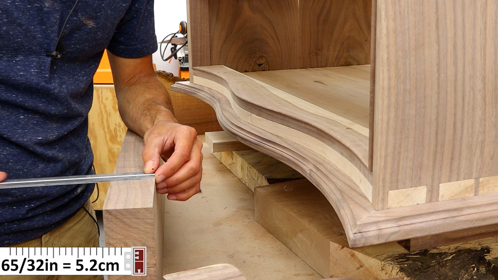
Now I keep the side foot in place and slide the front foot forward, so that it’s flush up front throughout the length of the template. I know for the top area where the foot is going to be touching the case, it steps back 5/8 of an inch from the high spot, so I want to pull the stock forward another 5/8 of an inch.
![]()
If I come around to this side, I can see where my profile’s going to end up, because the side foot shows me exactly. I am past the glue seam by a little bit, so we have that much room to play with without contacting that glue seam.
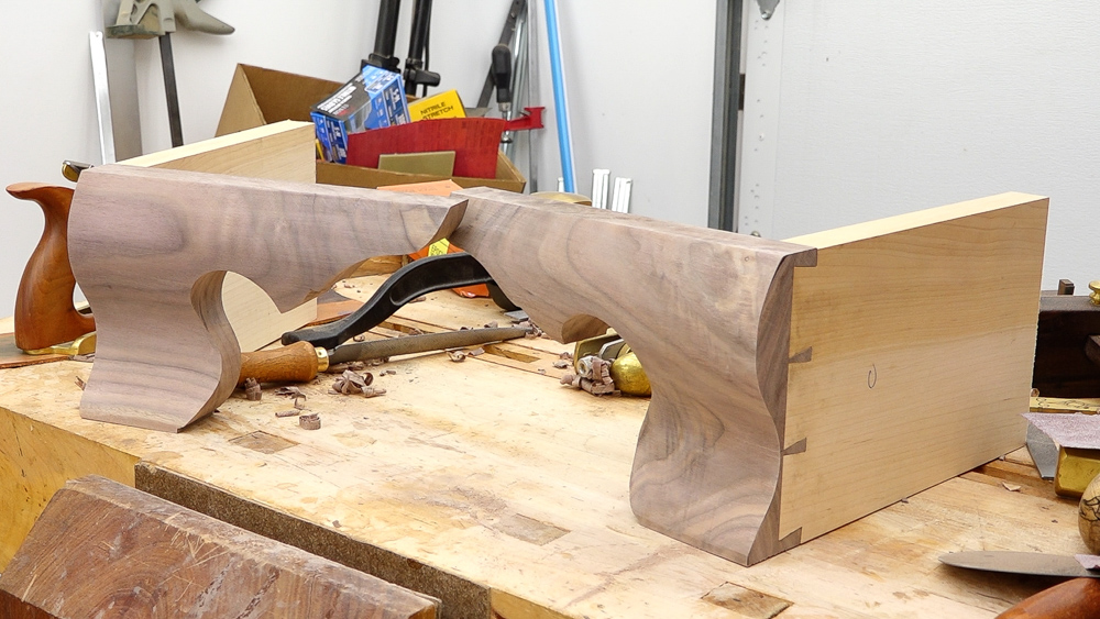
The curves on these front feet really elevate this piece quite a bit. These worked out pretty well, not really all that hard to do, which is very refreshing.
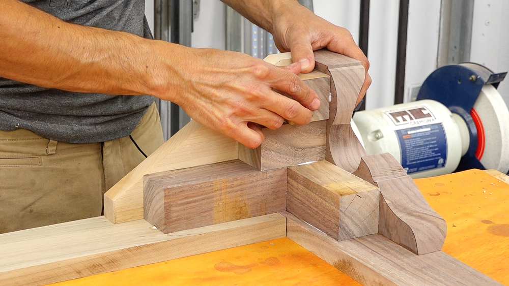
So from here, we’re going to get these things all finished up to be connected together. I’m guessing that these are going to need some tweaking on the miter joints, so I’ll tweak the miter joints and then cut in some floating tenons to join them together. From there it’s a little bit more shaping. You want to do the absolute final shaping once the feet are connected and glued together and assembled. That way you can make sure that the miter line between the two feet is super crisp and really, really nice.
Just about done with the shaping on these, and then we can talk about getting these things attached to the transition frame.
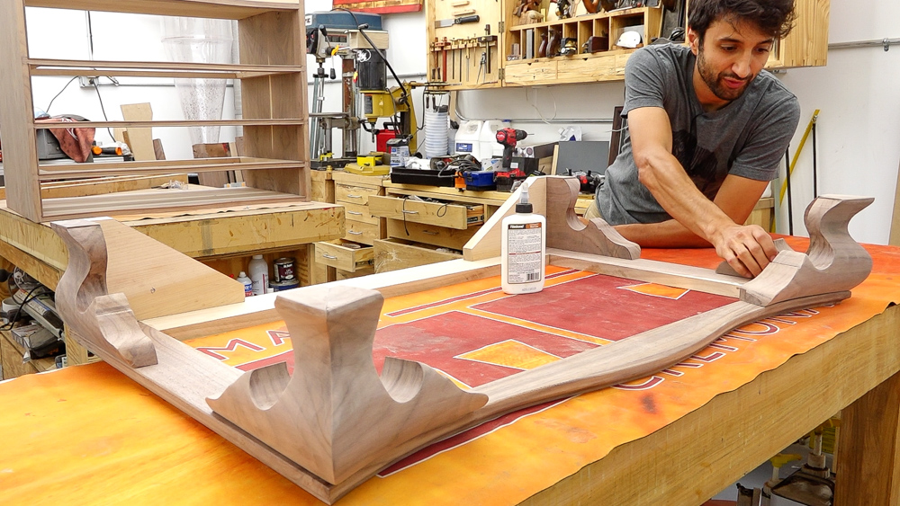
That takes care of all four feet. They’re ready to go on and get glued to the underside of the transition frame. I also lapped the top surface of all of the feet. It is very likely and common that the top surface is not flat, which will make it hard to attach to the frame. So I took these to the table saw, put a piece of sandpaper down on the table, and rubbed them around to get rid of all the high spots. That will get the whole top face of the feet into a single plane so they will sit down nicely onto the frame.
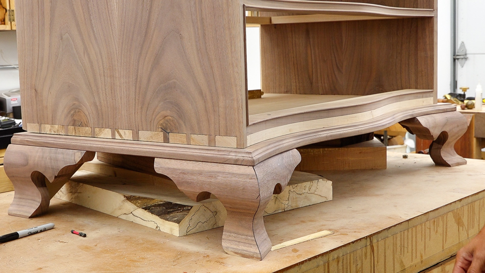
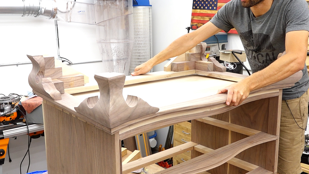
I’m going to go pretty easy on the glue. Don’t need to go overboard here. I don’t want any squeeze out towards the front, so I will hold the glue back from the front edge just to make sure I don’t have any squeeze out between the frame and the foot. These are just a rub joint, so I’ll set them down onto the frame, rub them around to get a little suction going from the glue, and the position them exactly where they need to be.
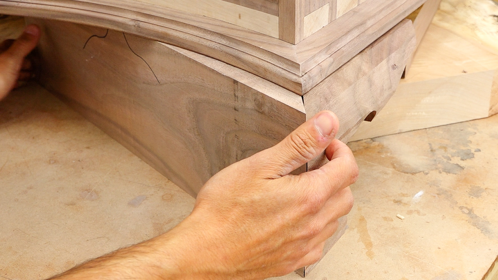
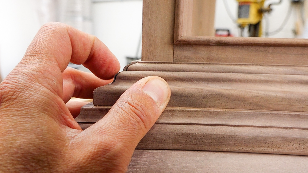
The feet are held back from the edge of the frame a little bit so there will be a bit of a shadow line. There is a round over on the underside of the frame and there is a curve on the foot, so I want the curve on the foot to be behind the round over on the frame. Now I’ll leave these alone for a little bit, and then we’ll come back and reinforce them with the glue blocks.
Glue blocks are a great, traditional way to get rid of some scraps. So these you can go for about here. And then I’ve got some that I’m starting for the front here. For the glue blocks, we can be a little more sloppy and generous with the glue, since we are on the underside of the case, which won’t be seen. Doesn’t really matter if there’s squeeze out back here.
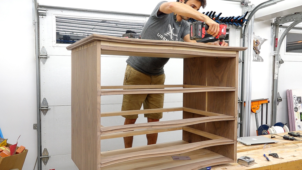
On the back feet, because I have a space, I’m going to continue layering on some blocks and building up that corner. Normally this is done on the front and the back feet, but my front feet are pretty narrow. You can see that I’m alternating the grain direction as well. That way I have my long grain connection between every other layer to the feet or the bracket.
Now this is ready to go on. I’ll glue along the front, and then in the back, I have some holes drilled. They have an oversize hole through them, so the screw I put down there has a little bit of wiggle room. That allows the case to flow in and out underneath the backside of the base.
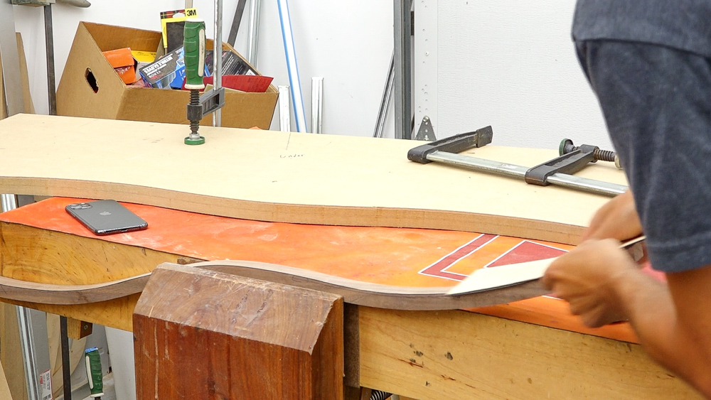
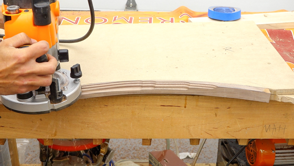
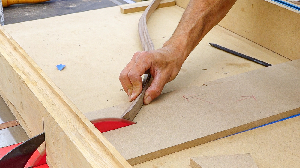
Now we can move onto the transition molding, which will cover the bottom of the case. You know what that means: more templates! This time I need the inverse or negative of the case. We can use the router to make this nesting template. I have a 1/4-inch flush trim bit in a table riding along the template for the case. This bit is removing a 1/4-inch of material so to get a perfect nested template, we need to add back that 1/4 inch.
We’ll take this new template with that 1/4 inch missing and make another template from it. I use a washer to mark the rough offset so I can bandsaw away most of the waste. In the router, I have a 1/2-inch bit and a one inch bushing. That combination gives me a 1/4-inch offset and essentially puts back the material that was removed from the curve with that 1/4-inch bit in the router table.
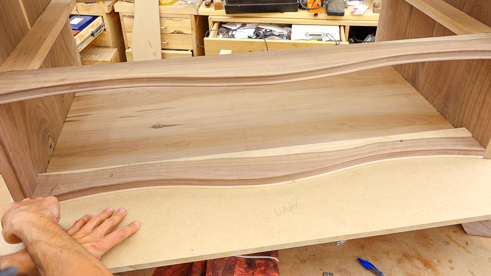
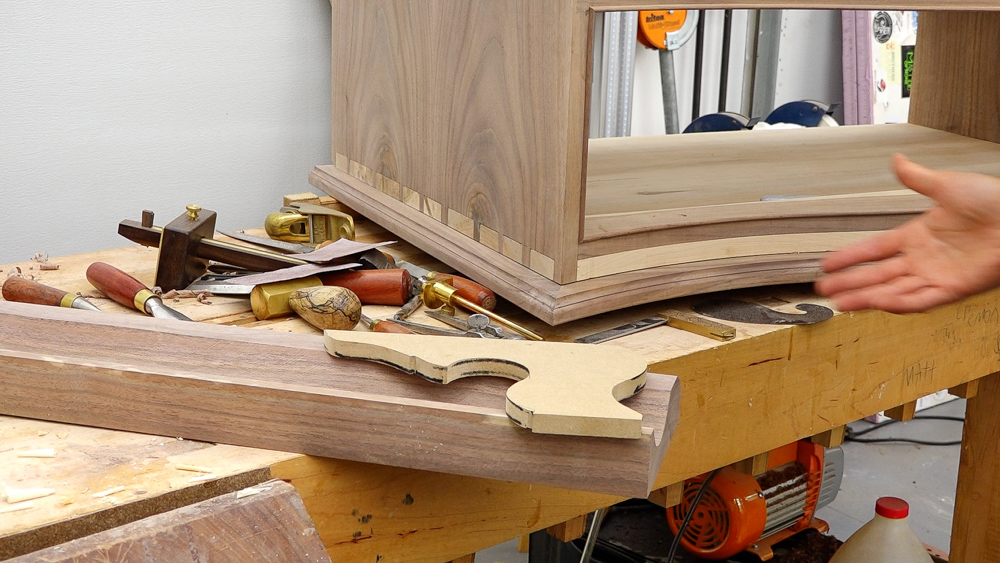
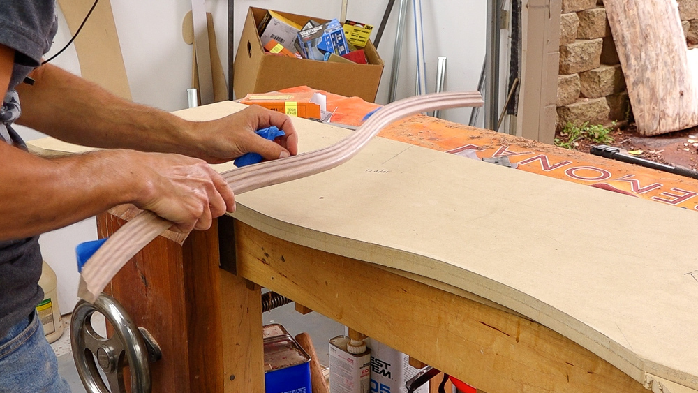
Here is the completed template, and it fits fairly well.
So let’s move forward and make some actual molding stock.
Okay, let’s see. We’ve got a really nice fit along the top here, which is what really matters. So from here, I’m going to fair this curve a little bit because it’s a little bit bumpy from my work on the spindle sander.
Then we’ll cut the profile into it, do some sanding, and then we can see how it looks on the case.
This is a pretty small thing, but this might be one of the coolest things I’ve ever made. It’s just a piece of molding, but it is cool. I like it when some random plan I have that may work in theory actually works out.
Next let’s miter this. That actually went surprisingly well. Now I’m going to do the same thing on the other side.
Next let’s make this molding for the side, which should be a lot easier because it’s straight.
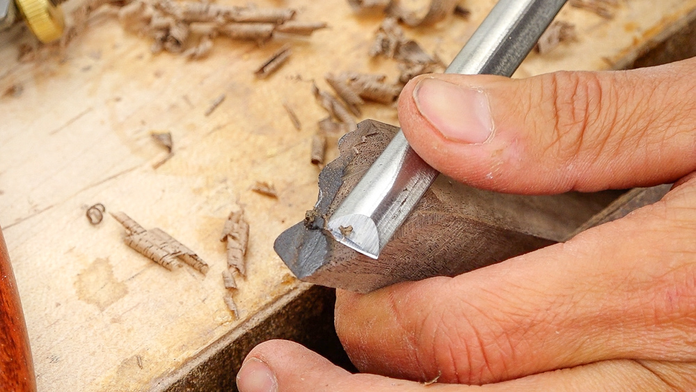
Now we start getting into the fun fudging time. These obviously aren’t going to match up at this corner, so we need to adjust the profile of the return molding to match what’s going on at the miter. On this lower bead, I could just fudge this right at the corner and carve this material back and fade it in. That wouldn’t be too noticeable. But the second bead up here is going to be far more noticeable if I do that. So I’m going to transfer the profile onto the end grain and carve the profile into there by hand.
For now I think we’ll go ahead and start gluing things in. I’m going to glue in the false bottom and the drawer supports for the bottom drawer, and then we can get the front molding attached to the case.
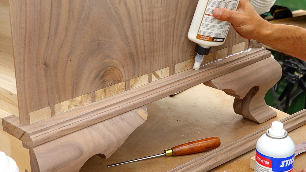
Okay, let’s get this front molding applied. I did put a little bit of a back bevel on this front molding. That’s going to get that material on the molding out of the way so we can make sure that we have a nice tight connection where the molding meets the top of the case here. I’m going to go through and apply a really light glue.
Last little detail here is the return moldings. So a few things on the prep. Before we install the molding onto here, the side of the case needs to be a finish-ready surface, which mine is. On the stock of the molding, we have a back bevel on here because this molding is straight. So when the molding gets installed, the bottom isn’t going to make contact with the case which ensures that the top makes contact with the case, making that nice and tight. Another thing that makes us a lot easier is that on the ends, I have removed all of the material that I do not care about. Everything except the very little bit of the edge of the profile is still there. As I’m doing my tweaking, all I’m doing is just adjusting that small band of material towards the outside of the molding.
Then it can be glued on. With this, we want the case to be able to float behind it, so I’m not going to glue it to the case, except for right at the corner and just a few inches off the corner. Then it will only be glued to the frame beneath it for the rest of the length.
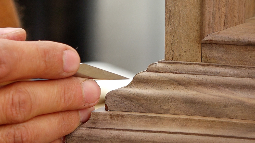
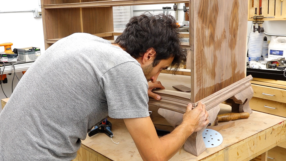
Now right here, all this end grain is the material I need to remove in order to get these profiles to be perfect and crisp right at the corner.
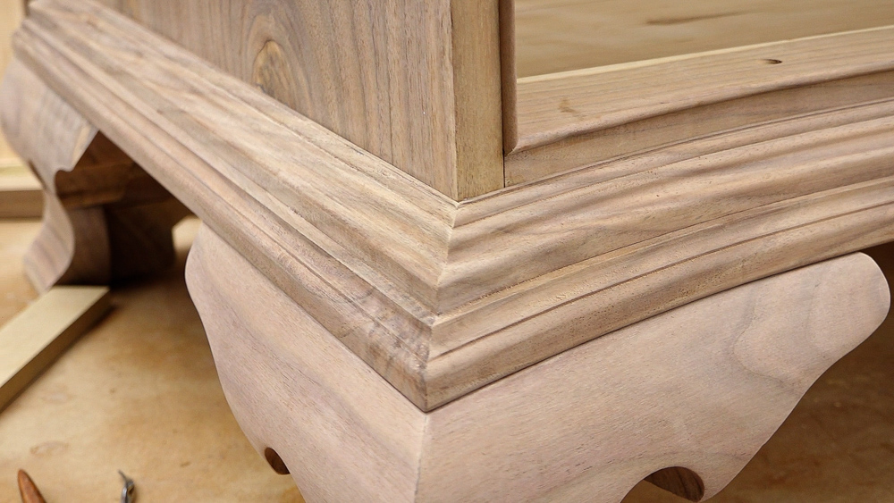
Okay, there is the completed corner, and you probably wouldn’t know that these two profiles didn’t match up before. So that takes care of the transition molding!
So yeah… that was a lot. But just like everything else with this project, this simple wavy curve here on the front makes everything just a little bit more complicated.
If you like these more in-depth woodworking videos, definitely check it out my classes over in the guild. I have over 150 videos spread over nine classes over there. This time we’re going to highlight the waterfall tables. Not only is this a great introduction to live edge furniture work, you get to execute that amazing waterfall joint, which causes the grain to seamlessly flow over the corner of the table. Another thing we do in that series, which is similar to what we did here for the base, is the glass inlay. We go through the process of inlaying basically any shape you want. In this case, it was a custom piece of glass into the table. And that’s just more of that router magic that we did similar to here to make our negative template of the front of the case.
And again, if you want to make your own serpentine chest of drawers, I do have a full set of plans over on my website that you can check out as well. That’s going to do it for this one. Next time we’re going to do all of the last little things, which there’s a lot of. We’ll make the top and we’ll do all the finishing and make the back boards, make the drawer bottoms, put the hardware on, all that kind of stuff.
Thank you as always for joining me, I greatly appreciate it. If you have any questions or comments on the serpentine chest of drawers or anything here in my shop, please feel free to leave me a comment. As always, I’d be happy to answer any questions you might have. And until next time, happy woodworking!
Welcome to my shop! This is a quick update to let you know what I’ve been up to. This big chunky thing is the leg

Welcome back to the home renovation. This time I’m going to be working on the kitchen island. Here is a small model of the island.
Welcome back to our home renovation. Today I am going to be working on this wall. It needs some upper cabinets and the surround for