Kitchen Island, Barn Power – March 2024 Update
Welcome to my shop! This is a quick update to let you know what I’ve been up to. This big chunky thing is the leg
The last piece that needs to be added before the mill can be tested is the tensioner. The tensioner will move the idle wheel out and away from the drive wheel putting tension on the blade. There are many ways to accomplish this. I will be using a simple hydraulic ram and hand pump so I need some way of holding the ram and I need something for the ram to push against.
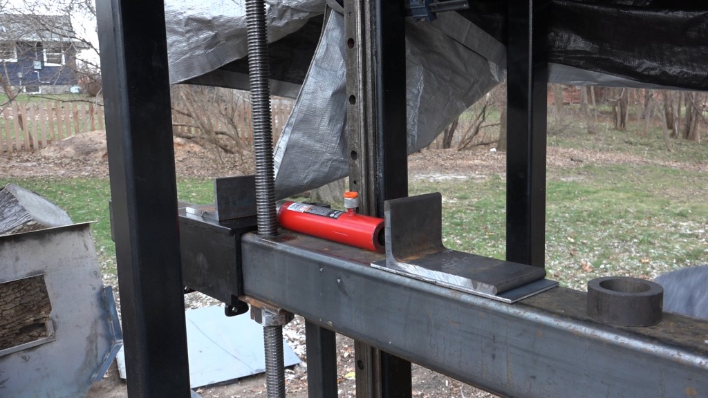
Here is a rough layout of the tensioning mechanism parts. The central component is a 10T hydraulic ram which is way bigger than is needed here but is cheaper than smaller options. The ram will be positioned between two pieces of uneven leg angle. The piece on the beam is 4″x8″x.5″ and the beam will also receive a plate to thicken the attachment area. The angle on the idle mount it 3″x6″x.5″ and will be bolted directly to the idle mount. A piece of round tube will be welded to the beam’s angle to hold and position the ram and there will also be a piece of rectangular tube placed in the middle of the ram to help hold it in place. All the steel for this area came from the offcuts bin at my steel dealer.
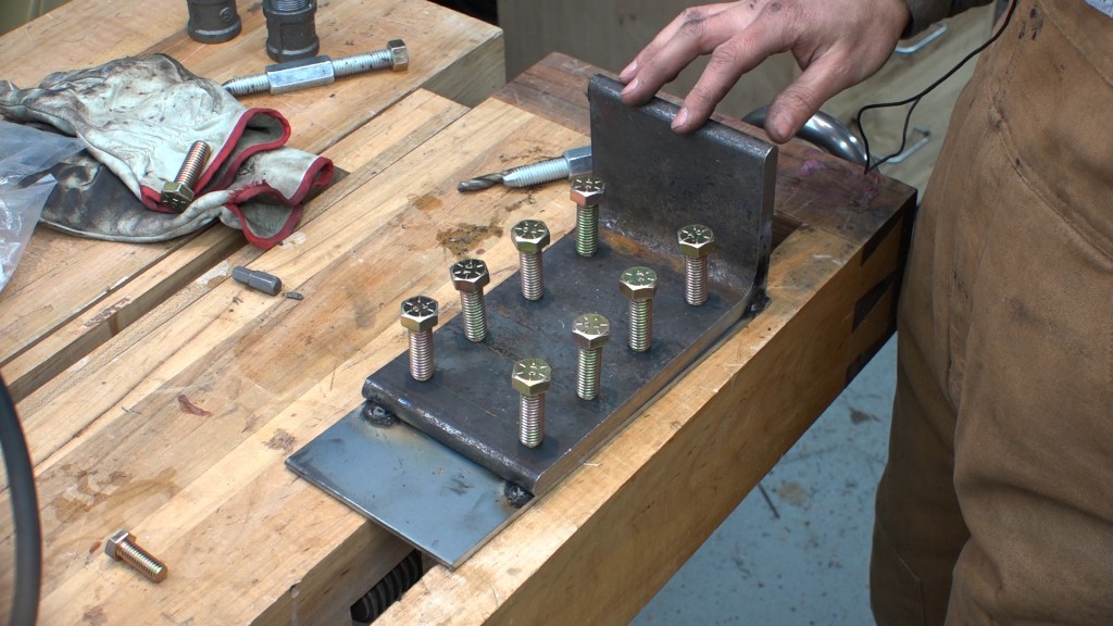
To make transferring the hole locations easy, I tacked the filler plate to the bottom of the angle. Once the holes are drilled trough both, I can disconnect them and I’ll have an exact template of the hole locations. I’m using 8 1/2″ bolts for aesthetic reasons – I think it looks cool. One bolt at each corner to hold the angle down would have been plenty. I eyeballed the spacing, marked, and drilled pilot holes through both parts.
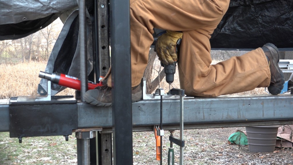
Next I took the assembly to the beam and clamped it in place with the angle square to the beam. Once I was happy with the placement, I could drill the holes through the beam using the existing holes as a guide.
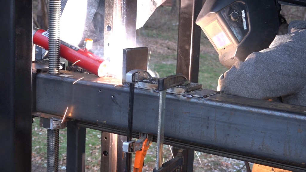
With the pilot holes drilled, I can tack the plate to the beam.
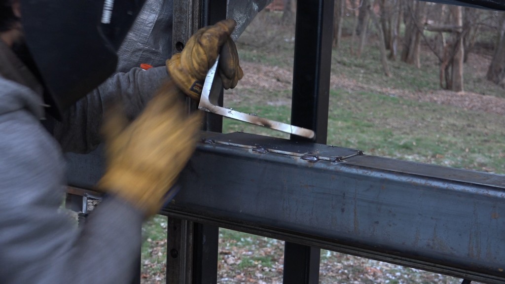
And break the tacks holding the angle to the plate. From this point, I can drill the holes in the angle up to 1/2″ and drill and tap the holes in the beam for the 1/2″ bolts.
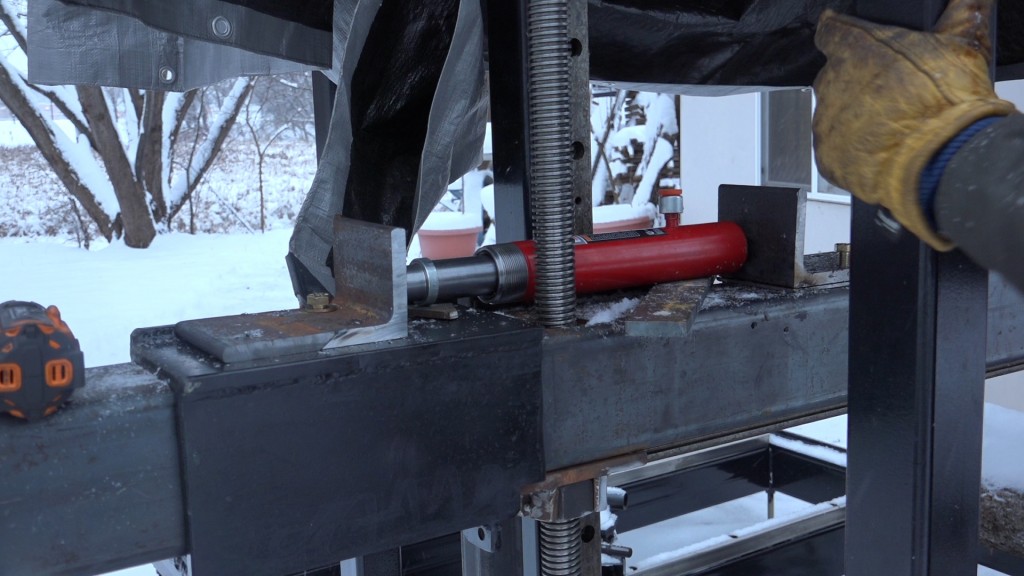
Now onto the idle side. I attached the angle with one bolt to start so I could make sure I got the alignment right. I want the ram to press into the angle squarely so the force is evenly distributed.
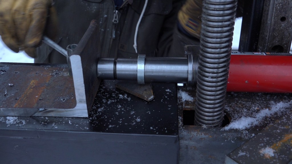
With the bottom of the ram sitting correctly on the beam side, I could slide the idle mount over into the other end of the ram. That caused the angle to pivot around the one bolt and become aligned correctly with the ram’s head. I could lock down the bolt and drill and tap another hole. I just did one more to start so I could make sure that nothing shifted.
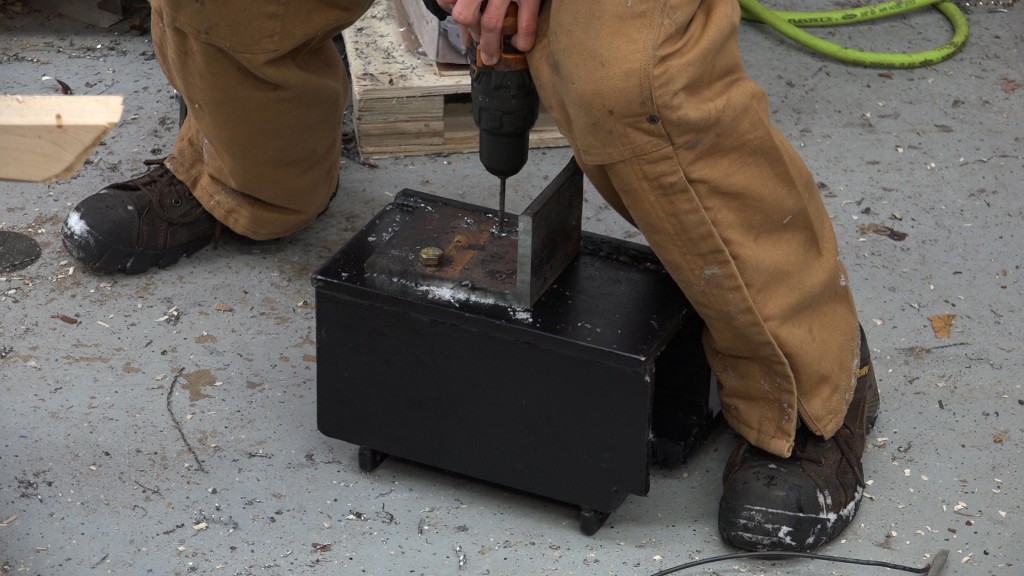
After replacing the idle mount, the ram alignment still looked good so I could proceed with drilling the other 6 holes.
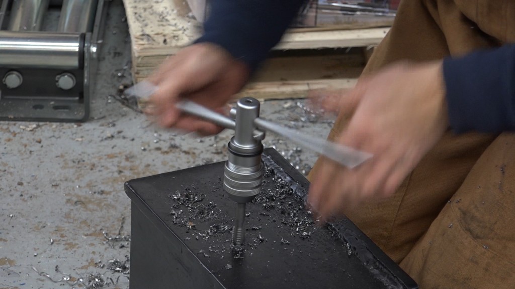
The angle had it’s pilot holes drilled out to 1/2″ and the idle mount had it’s holes drilled and tapped for the 1/2″ bolts.
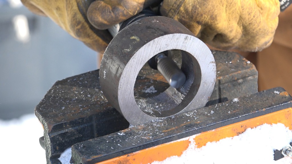
Next was the round tube. It was a little too small for the end of the ram to go down into so I enlarged the ID with a rotary file in a die grinder.
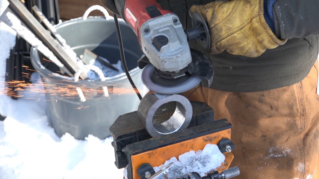
Lastly, the wall thickness on the pipe was a little too big and would position the ram higher off the beam than I had wanted so I ground some material away to create a flat spot.
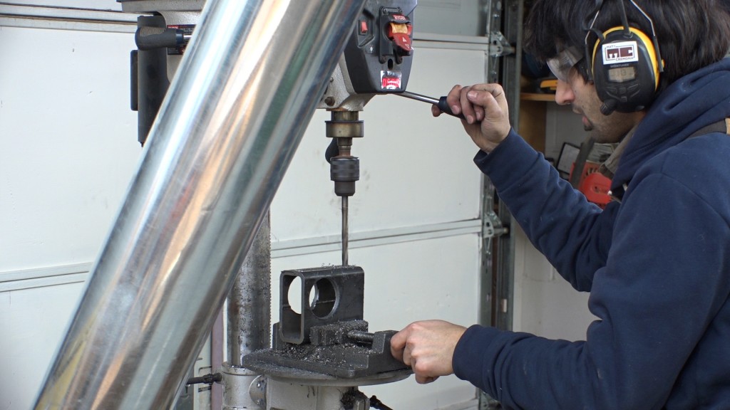
The last part was the middle ram mount. This will set the height of the ram off of the beam and hold the ram in position as it is extended. Two holes were drilled in this for the ram to pass through and two holes on the underside are used to bolt it to the beam.
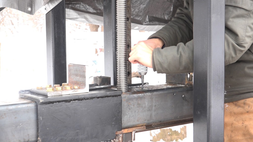
The middle mount get bolted to the beam with 3/8″ bolts.
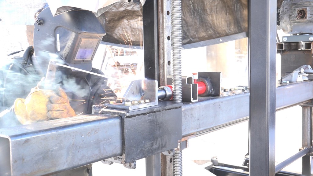
I got everything into position and tacked the pipe in pace on the beam side and I also added some braces to the angle. I don’t know how necessary these braces really are due to the heavy gauge of the angles and the relatively low position of the force but I was able to use up a couple scraps and welding practice is always useful.
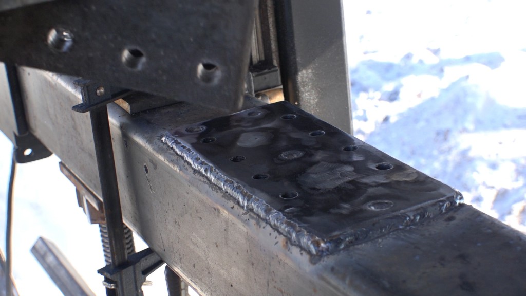
The beam plate received a weld bead around it’s perimeter as well as 6 plug welds.
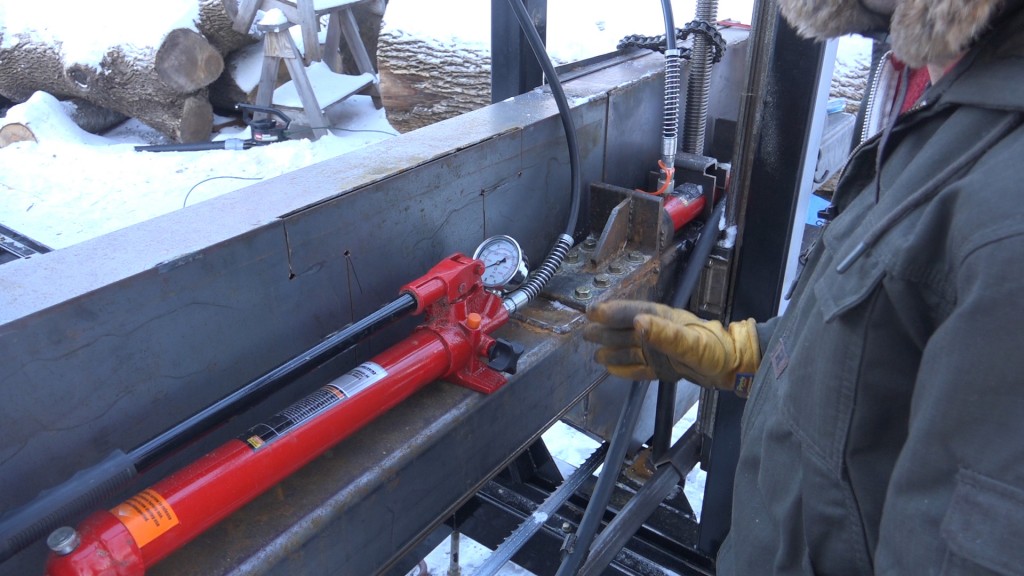
Here’s a look at the mechanism with the pump installed.
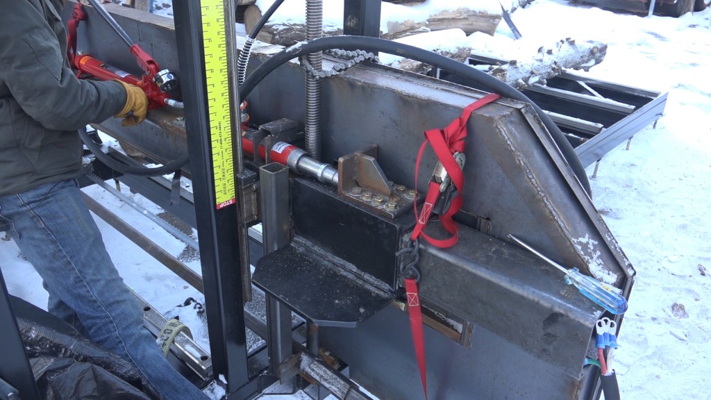
And a view from the other side.
I have to admit, I am quite surprised how well this works. The gauge on the pump allows me to monitor the pressure while the saw is in use and one issue I thought I’d have with this cheap ram and pump was some backflow as the ram sat under pressure. I tested this by leaving the blade tensioned over night and in the morning the reading on the gauge hadn’t changed. I was thinking I’d have to add a valve to prevent that but that might not be as high of a priority as I had anticipated. I still would like to make this system more dynamic so the tension stays consistent if the blade stretches or if sawdust builds up on the wheels. A few people have suggested that I simply add a hydraulic accumulator to the system and that seems like the best route to go.
Next time we’ll start tuning up and calibrating the saw which consists of aligning the wheels, tracking the blade, setting the tension, and setting the blade guides.
Lincoln 225 Welder: http://amzn.to/2cvOrfU
Triton Super Jaws XXL: http://amzn.to/2fPJCm9
Triton Super Jaws: http://amzn.to/2eB0smV
Triton Engineers Jaws: http://amzn.to/2ftAyPE
Super Jaws Side Support: http://amzn.to/2eB18Zv
Triton T20 Drill: http://amzn.to/2eqsmyD
Transfer Punch Set: http://amzn.to/2fiAQ0H
Tap Magic Xtra Thick: http://amzn.to/2c4E0j0
Cobalt Drill Bit Set: http://amzn.to/2bYIRnR
Rotary File: http://amzn.to/2jBAvmI
1/2-13 Tap: http://amzn.to/2jcTaJi
2 1/4″ Hole Saw: http://amzn.to/2jd6CwR


Welcome to my shop! This is a quick update to let you know what I’ve been up to. This big chunky thing is the leg
Welcome back to the home renovation. This time I’m going to be working on the kitchen island. Here is a small model of the island.
Welcome back to our home renovation. Today I am going to be working on this wall. It needs some upper cabinets and the surround for
One Response
Greetings from tropical Seattle Matt,
Boy and I think doing my job in 30 degree weather is cold, Seattle has turned me into a real weather wimp.
The cold won’t effect the hydraulic oil in the ram? I guess not but I don’t know much about hydraulics.
Now get out of the cold and go work with some wood in that heated shop.
All the best, Doug Lidz