Kitchen Island, Barn Power – March 2024 Update
Welcome to my shop! This is a quick update to let you know what I’ve been up to. This big chunky thing is the leg
Now that the skeleton of the carriage is built, I can start adding the saw head to it. The beam that will support the wheels needs to be guided through it’s up and down travel so I’m adding a center upright to the carriage to carry those guides.
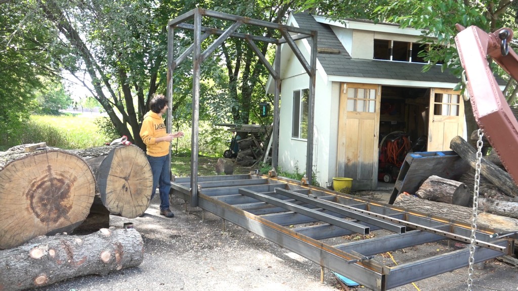
Here’s how we left things from the last part. The carriage frame is ready to start receiving the saw head.
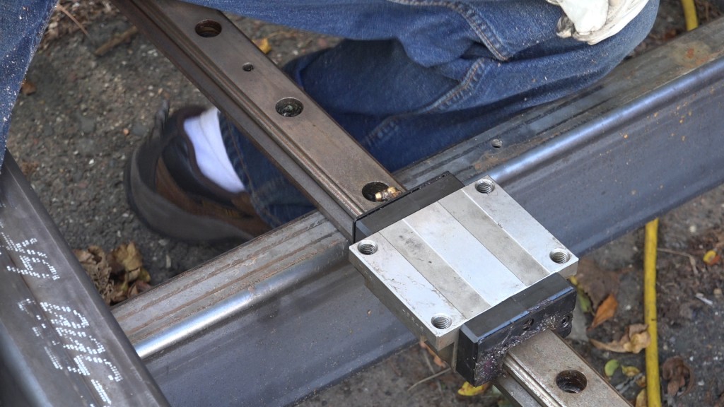
The saw head will need to be guided up and down. Originally I was going to achieve this by welding a box around the tube (I’ll still be doing this for the tension mechanism) but I received these THK HSR45 linear bearings and rails from a friend who was looking to get rid of them. They have no slop so they will do a good job of keeping the saw head from racking through the cut. The linear rails will mount to another piece of 3x3x.25″ tube that will be placed between the uprights.
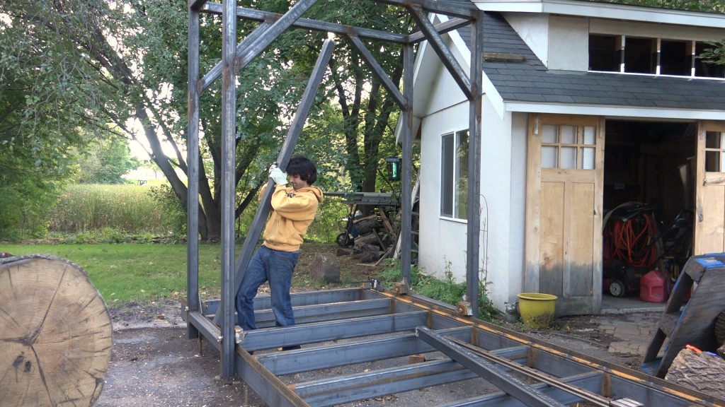
When James was here helping me with the carriage, he also cut and fit the uprights. I forgot to label them so I had to check to see which was the left and which was the right.
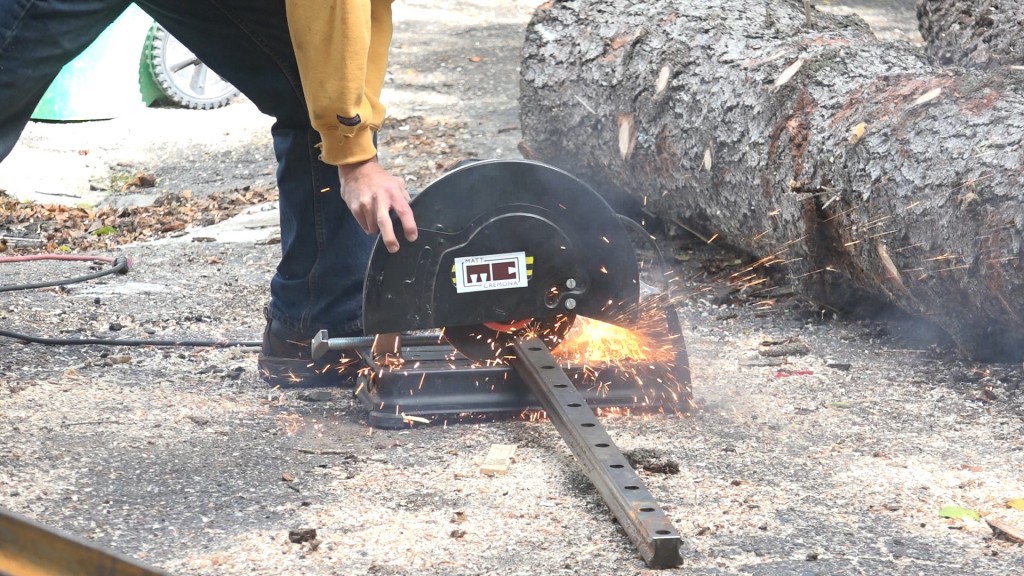
I determined how much length I needed for the rails and cut them to length with the abrasive chop saw. I don’t need the rail to extend fully from the top to the bottom. At the bottom I need space for the linear carriage to slip onto the rail and the travel is limited on the top and bottom due to the diameter of the wheels. Since the wheels will be mounted to the bottom of the beam, the offset is different on the top and the bottom.
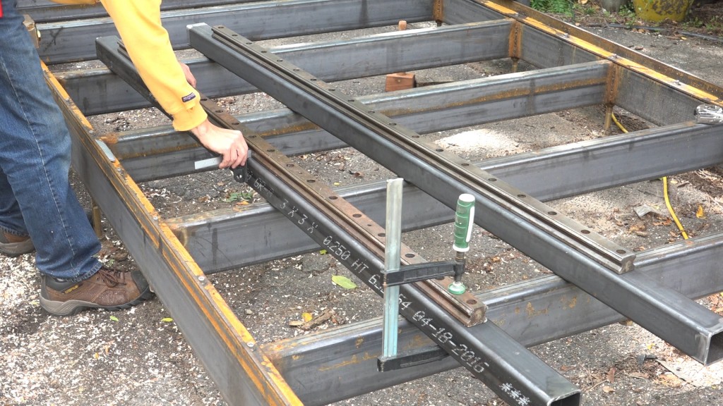
Next, I laid the rails onto the uprights and centered them along the width.
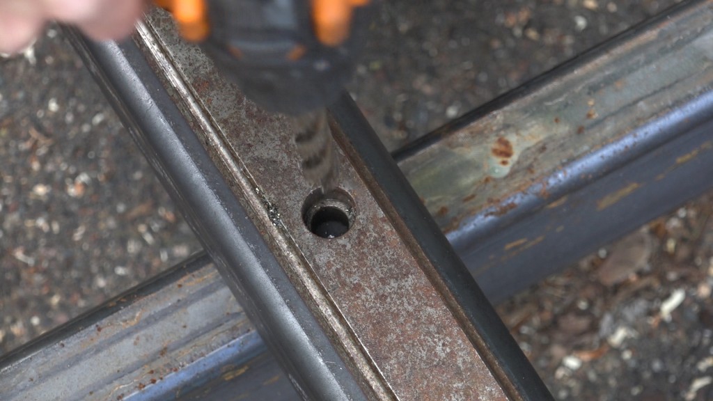
I’m going to be mounting these with 3/8-16″ socket head cap screws which give me 1/8″ of play to get the two rails aligned. The counterbore on the front of the rail is the right size to receive the 3/4″ diameter washer. To transfer the hole locations, I used a 1/2″ drill down the mounting holes to make a divot that my pilot bit would follow. I found this much easier than using a transfer punch since the pilot bit follows the divot better.
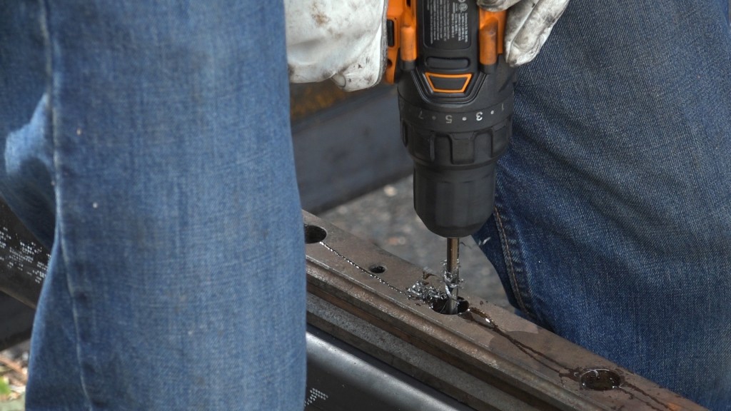
I drilled the 1/4″ pilot hole leaving the rail in place as a guide so I could make sure I was drilling squarely.
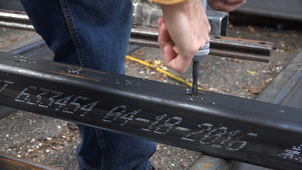
I then removed the rail, enlarged the holes, and tapped them for the socket head cap screws.
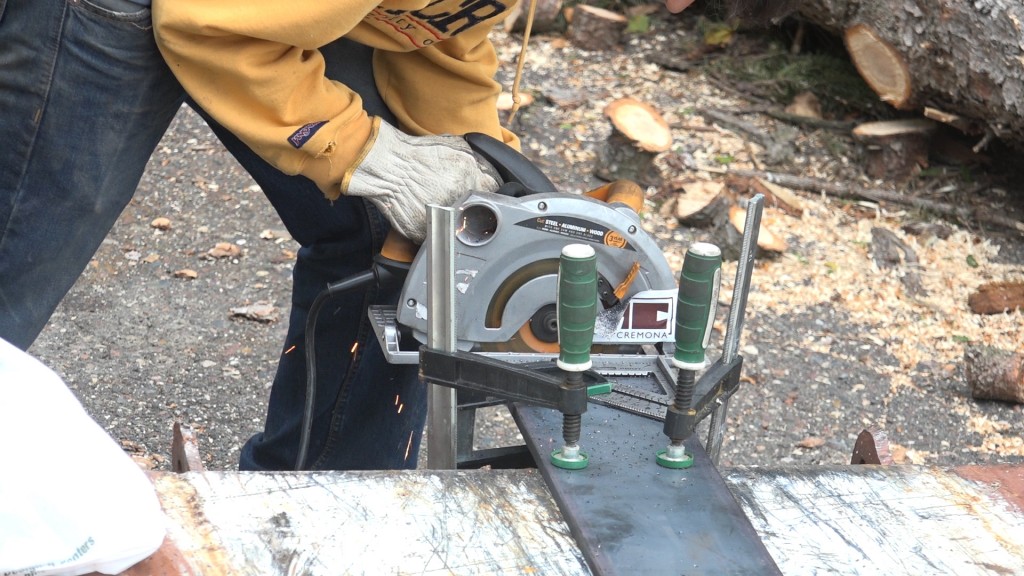
The mounting plates are 6×6″ that I cut from a piece of 1/2″ bar stock with my metal circular saw. I’ll also be using this stock to build the tensioning mechanism.
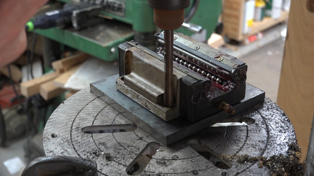
The carriages have M12 taped mounting holes. I don’t need the treads so I had planned to drill out the treads and enlarge the holes to 1/2″ but since the steel on these carriages is hardened, my drill bits didn’t even bite. So instead, I decided to leave the treads in place and use a 3/8″ bolt to mount them. To start making the mounting holes, I found a bit that fit best down through the threaded holes and made a divot to transfer the hole center location on one of the mounting holes. I then drilled and tapped that hole and then ran the bolt down through the mounting hole and threaded it into the plate. Next I repeated the process for the mounting hole on the opposite corner. Once I had the carriage attached to the plate in two locations, I transferred, drilled, and tapped the other two holes.
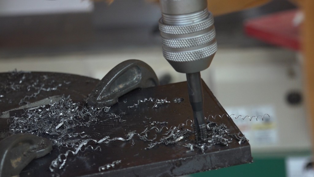
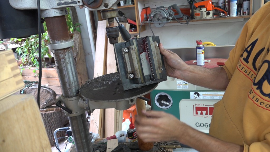
The carriage mounted to the plate. The last thing I did to the plate was to clean it up with a flap wheel and round the edges and corners.
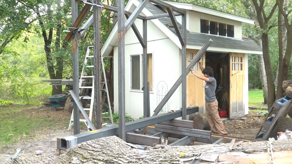
Now all the prep work is done, I can start installing the uprights. I’m going to get them into position and just clamp them in place. I’ll then use the saw beam with the linear carriages to align the linear rails.
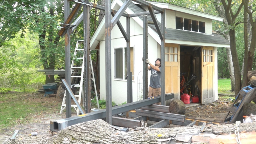
So with the rails attached to the uprights, I can lift them into position. These were incredibly heavy with those rails attached. I decided to attach the upright in the center of the carriage as that will still give me plenty of room to change blade. I’ll have around 6″ between the wheels and the front upright. I got the uprights into position and clamped them in place with some angles as braces.
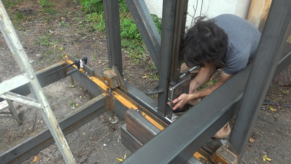
Next I slide the bearing carriages with their mounting plates onto the rails and clamped a block of 2×4 to the upright to keep the carriage from falling off. I need to come up with a better way of installing these bearing carriages because I ended up with 6-8 balls falling out of each.
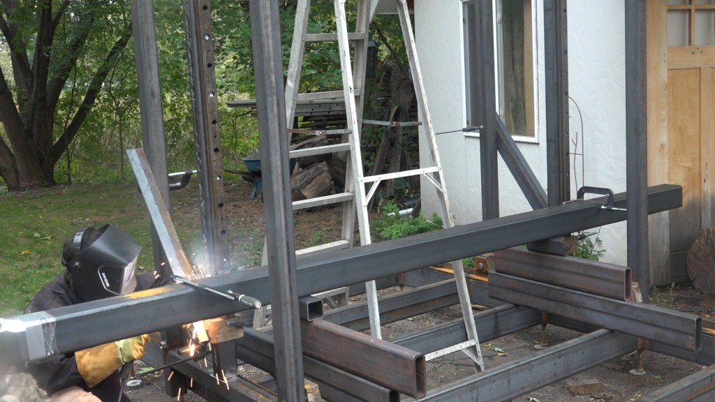
Next I lightly welded the beam to the mounting plates. I didn’t want to distort the plate or damage the bearing so I keep the heat minimal.
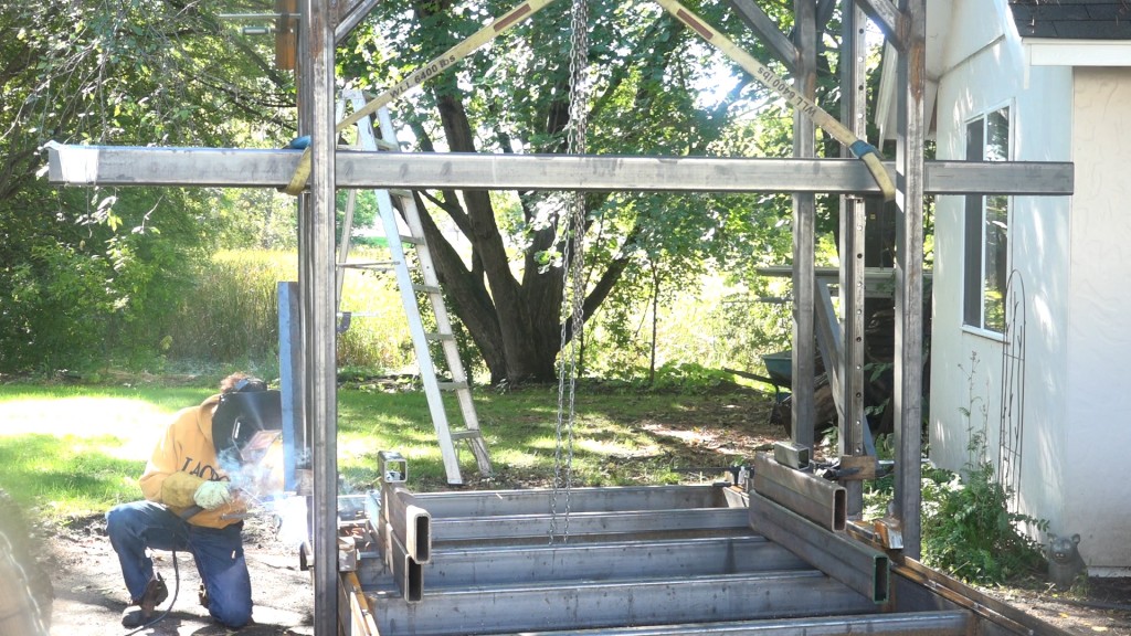
Next I used a chain hoist to lift the beam up and down the rails to get them aligned. Then I went back and tack welded the bottom of the upright, moved the beam up and down again and tacked the top. I repeated this process to gradually weld around all sides of the uprights so I could be sure I wasn’t having any issues due to distortion.
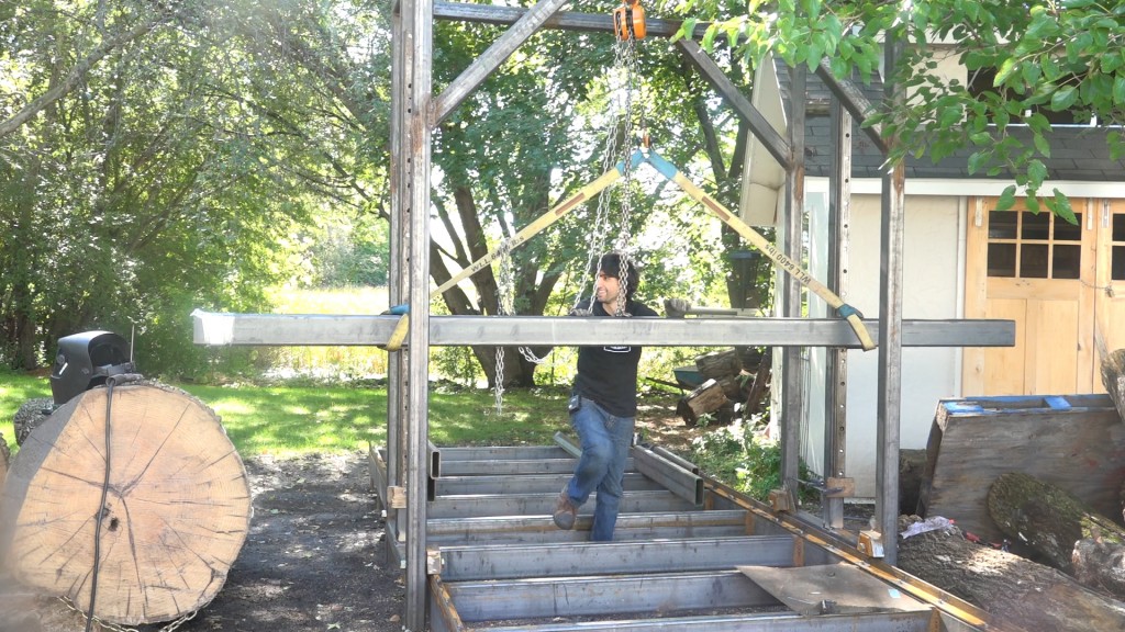
The last thing to do was give it a push down the track. The added weight really makes this roll a lot smoother than it did before so when I add all that weight to the saw beam it should get even better!
Tap Magic Xtra Thick: http://amzn.to/2c4E0j0
Triton T20 Drill: http://amzn.to/2bQ1ZkV
Cobalt Drill Bit Set: http://amzn.to/2bYIRnR
Metal Circ saw: http://amzn.to/2c3DaSS
Lincoln 225 Welder: http://amzn.to/2cvOrfU
[Amazon links are affiliate links]


Welcome to my shop! This is a quick update to let you know what I’ve been up to. This big chunky thing is the leg
Welcome back to the home renovation. This time I’m going to be working on the kitchen island. Here is a small model of the island.
Welcome back to our home renovation. Today I am going to be working on this wall. It needs some upper cabinets and the surround for