Kitchen Island, Barn Power – March 2024 Update
Welcome to my shop! This is a quick update to let you know what I’ve been up to. This big chunky thing is the leg
The bandsaw mill has been sitting under a tarp since I took it apart last summer to paint the guards and sawhead beam. This time, we’ll push forward with the reassembly and start taking care of some small details.
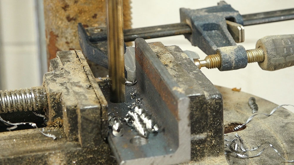
The first thing I want to knock out are the carriage stops. Previously, I had a c clamp clamped to the track to act as a stop for the carriage. Although effective, it’s not the best looking solution. I had a length of 2x2x.25″ angle from when I built my outdoor fireplace. This angle was used to support the chimney flue. The carriage really only needs 2 stops – one on each end but since I had the stock for it, I made four – one for each corner. These were cut to 4″ long, 13/32″ holes were drilled and the outside corners were rounded off.
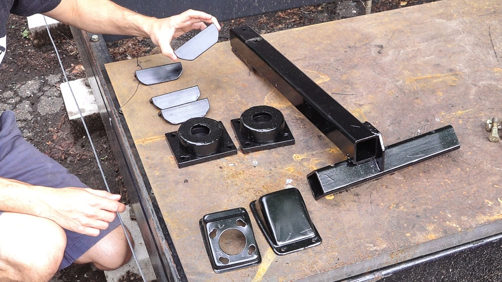
I had a few parts left over from the last post that still needed paint so while I was getting paint applied to the carriage stops, I also applied paint to the thrust bearing holders and covers, the support for the idle side blade guide adjuster, and the motor’s electrical box.
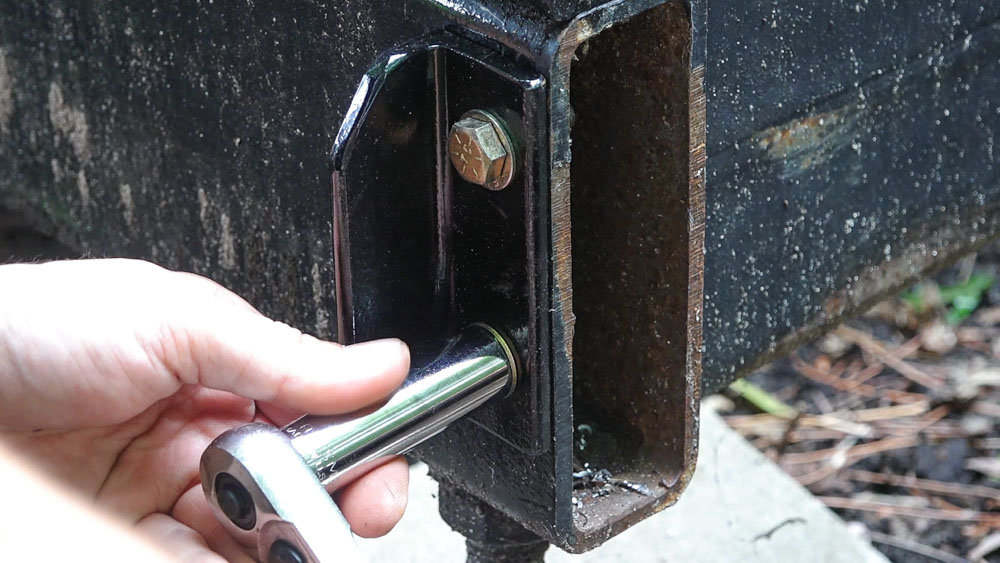
The carriage stops are installed at each end of the bed’s side rails. Holes are tapped for the two 3/8″ bolts and the stops are bolted on. The stops will contact the upright of the carriage and keep the wheels from rolling off the track if the carriage happens to get away from the operator.
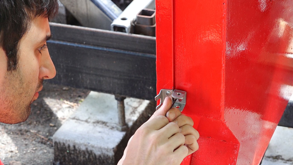
Next I need to start working on installing the lift mechanism which requires removing the guards and while I’m working with the guards, I want to replace the latches that hold the doors on. The ones I installed last time were not strong enough to hold the doors closed and most of the had failed. I’ll replace them with some all weather rubber draw straps with stainless hardware. The mounting holes were spaced differently and used #8 fasteners instead of #6 which I had previously used and I needed to place the hardware in different places so I wasn’t able to reuse any of the previously tapped holes.
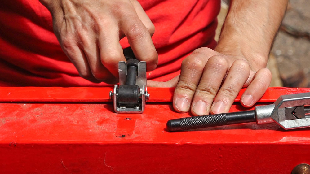
The two stainless pieces are mounted to the guard body and doors with #8 stainless button head screws. These latches are much better than the previous ones. They are able to apply much more force to the doors.
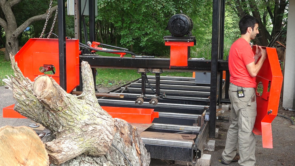
With that change out of the way, I can remove the guards and start working towards reinstalling the lift.
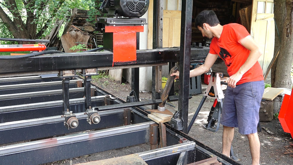
The sawhead has been resting on some posts since last time and those posts are blocking the location where the thrust bearings need to go. I placed my Super Jaws under the sawhead beam and removed the posts.
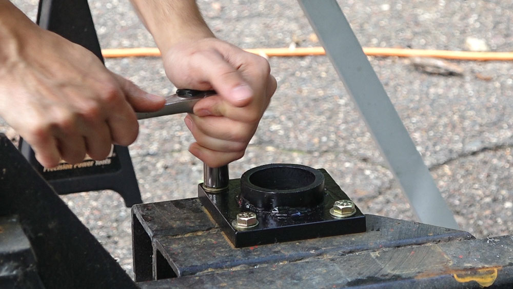
Now I can finally start on the lift mechanism. This starts with installing the thrust bearing plates. Before I removed these from the saw last time, I center punched the mounting holes onto the support platforms. So now, those holes can be drilled out and tapped for the mounting bolts.
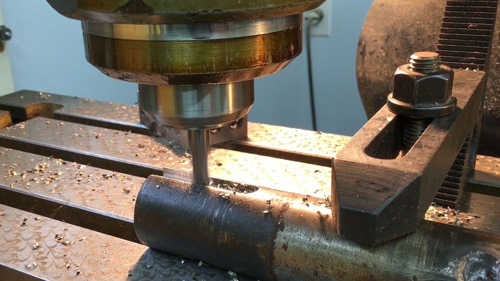
One thing that was still on my to do list was cutting the keyways into the acme rods to better lock into the extension posts on top and bottom. A local viewer offered to cut these keyways for me on his mill. He cut the 3/8×2″ keyways into each end of the acme rods and also replaced the keyways I had cut on the lower stepped shaft with an angle grinder. Thanks Carson!
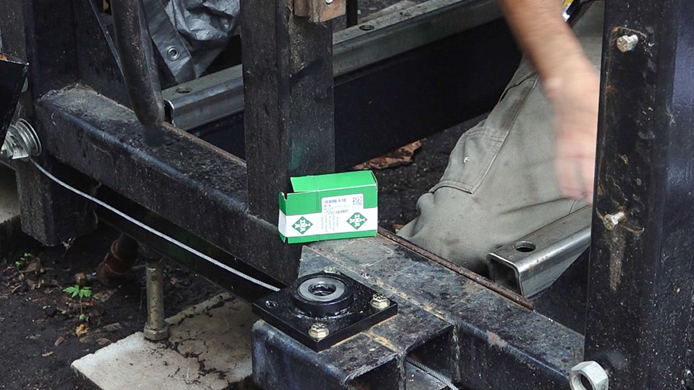
Into the bearing holders go the thrust bearings. Fresh ones!
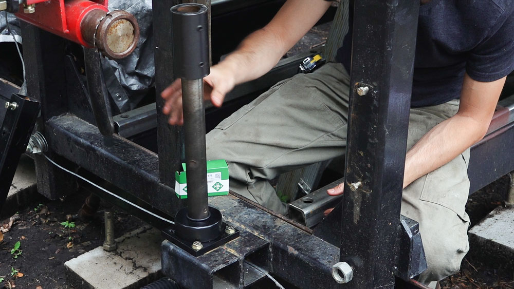
The stepped shaft with the coupler goes through the bearing guard and into the bearing. I had purchased a set of bellows which would cover the acme rods and compress down below over the stepped shaft but the ID of the bellows was too small to pass over the coupler. I’ll order a new set and install those in the future. For now, I have an O ring on top of the guard to help keep debris out of the bearing and I’ve covered the bearing area with grease.
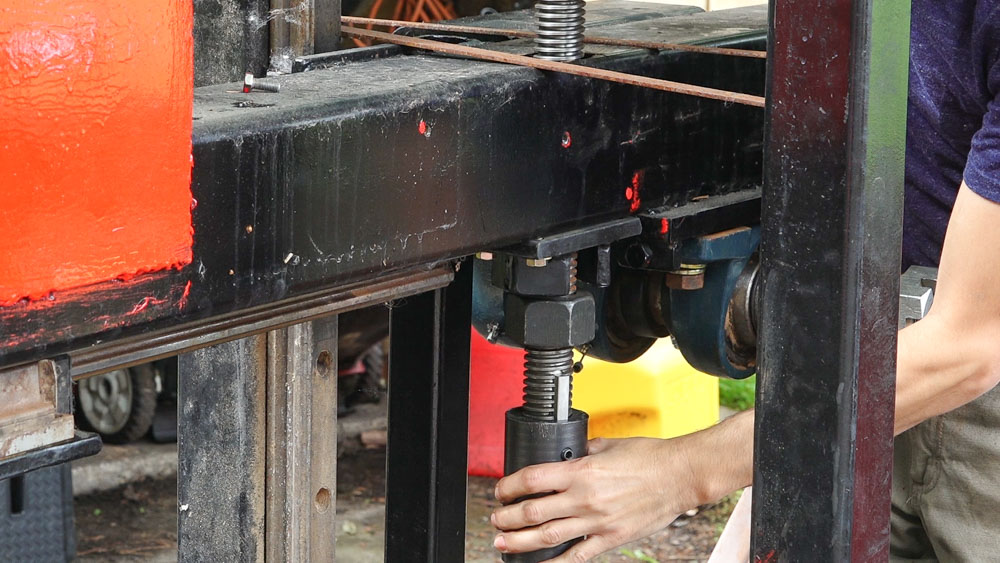
Next the nut retainers are bolted back onto the beam and the acme rods and nuts can pass through the beam and into the coupler. Having the keyway in the acme rod is going to be great. I no longer have to rely on the set screws to keep the acme rod coupled.
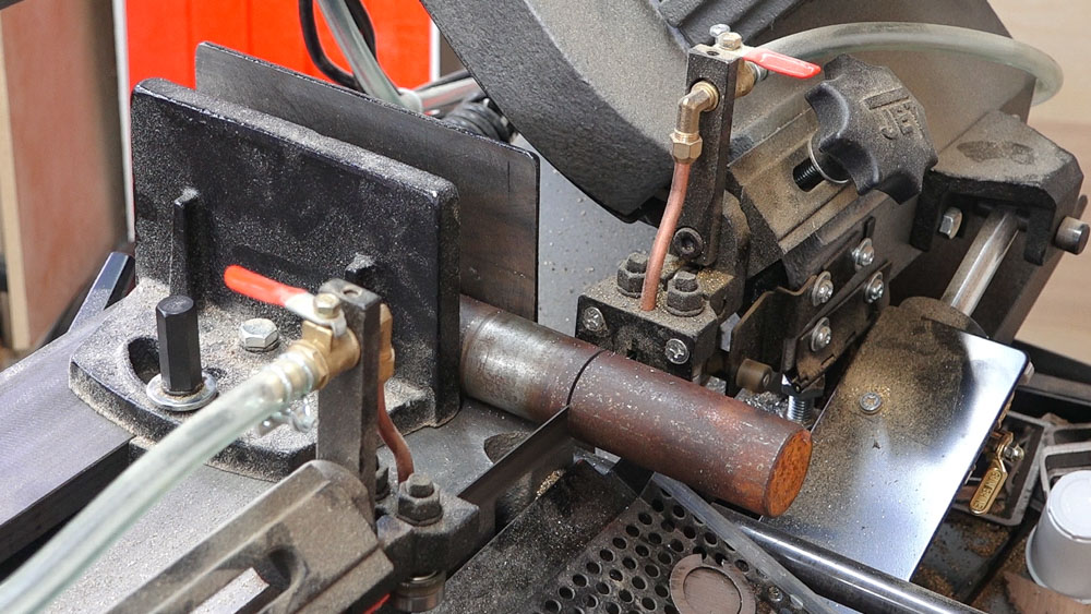
Next I can move on to the upper section of the lift. The shaft extensions that I added previously were left long just in case but now that I have things finalized, I can cut them down to final length so they’ll sit closer to the top of the carriage.
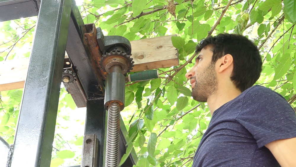
The linking sprocket can be reinstalled onto the shaft, the shaft assembly inserted into the coupler, and the bearing can be installed onto the shaft.
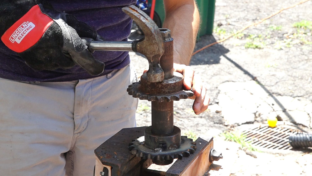
On the driven side of the lift mechanism, I previously had a 33 tooth sprocket being driven by a 13 tooth sprocket on the motor. This provided more reduction that I really needed which resulted in a pretty slow lift. I’ve replaced this sprocket with a 22 tooth. The motor will still have a bit of a torque increase but will also be much quicker. Once the sprokets are reinstalled, the upper shaft on the idle side can be reinstalled onto the mill.
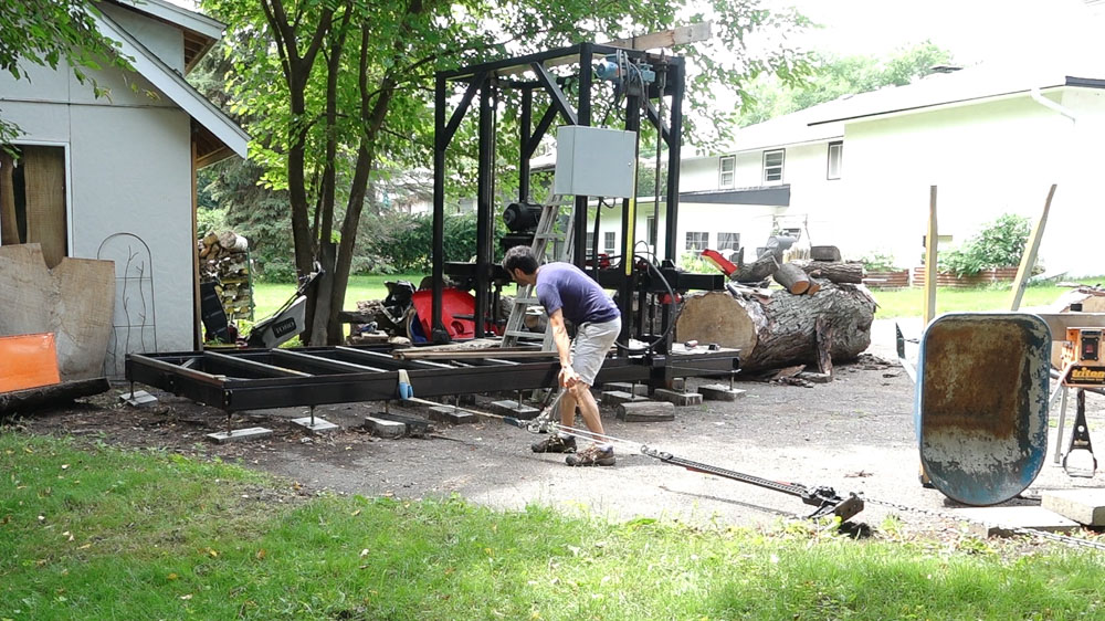
While I’m out here, one of the things that I’ve been meaning to do is move the mill and improve the feet. When I built the mill, I was limited in where I could put it because I had so many logs in my driveway. I was able to clear out just enough space to build the mill but that space was too close to my shed. With the carriage all the way back, I couldn’t raise the sawhead more than 3′ before the guards would contact the fascia of the shed. Moving the mill was pretty simple using a come-along to slowly pull the back end away from the shed. I raised all but 4 feet and put the back two into c channel to help guide them and reduce friction. The front idle side became a pivot point so that foot was left on its stainless disk and the last foot was placed on a steel plate so it could move a few inches and slide easily in the process. I moved the mill about 18″ away from the shed which gives enough clearance space and also improves the approach angle for my trailer coming down the driveway.
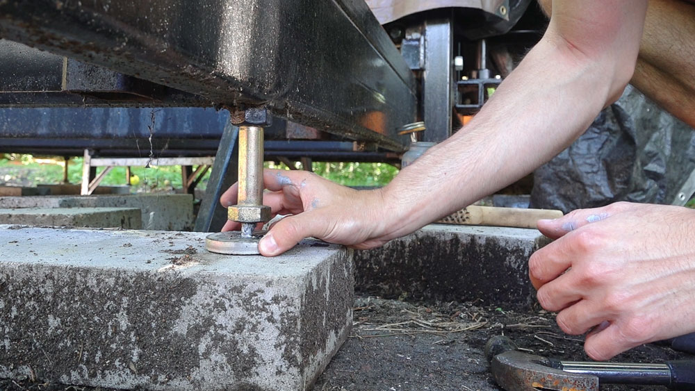
Lastly are the improved feet. When I first set these up, I used a round scrap of stainless steel under each foot. My thinking here was the disc would help distribute the pressure from the bolt head and when I needed to adjust the foot, the steel on steel would be easier to turn since there would be less friction. This less friction aspect was an issue. Whenever I’d winch a log onto the mill, the mill would end up sliding since the base had such little friction. Once time the bolts slid off the pads and started sinking into my asphalt driveway. I added the concrete blocks in case the bolt head happened to slide off again and to also provide a bit more ground clearance. The improvement I’m making to the feet is to pin the bolt and the pad together. A 3/8″ hole is drilled through the pad and a 3/8″ rod is pressed in. A wider hole is drilled into the head of the bolt so there will be some play so the pad will still make full contact with the concrete if the concrete isn’t parallel to the bed. I reapplied anti-seize to the bolts and reinstalled them into the bed. The pin also receives a coating of anti-seize before being inserted into the bolt head.
That’s going to do it for this one. Next time we’ll take a look at the upper section of the lift. I’ll complete the linking chain routing and fill you in on the lift motor.
Lincoln Welder: http://amzn.to/2y34pIE
Triton Super Jaws: http://amzn.to/2fgwynS
Triton T20 Drill: http://amzn.to/2bQ1ZkV
Tap Magic Xtra Thick: http://amzn.to/2c4E0j0
Degreasing wash: http://amzn.to/2e4E5TA
Metal prep wash: http://amzn.to/2e6ZnkR
POR15: http://amzn.to/2e71uoE
POR15 Top Coat: http://amzn.to/2dO5YBH
Center Punch: https://amzn.to/2KSkaLU
Drill Bits: https://amzn.to/2uclr6f
Hilift Jack: https://amzn.to/2J6pUwv
Plans for the sawmill are now available!


Welcome to my shop! This is a quick update to let you know what I’ve been up to. This big chunky thing is the leg
Welcome back to the home renovation. This time I’m going to be working on the kitchen island. Here is a small model of the island.
Welcome back to our home renovation. Today I am going to be working on this wall. It needs some upper cabinets and the surround for
4 Responses
Hi Matt Where did you get your band wheels ? And what size are they ?
30” wheels from cooks saw
MAT did you ever put a set of plans together for this mill or your trailer ?
Plans for the saw are here: https://mattcremona.com/shop/plans/wide-cut-bandsaw-mill-plans
Still working on the plans for the trailer.