Matt's Weekly Shop Update
Kitchen Island, Barn Power – March 2024 Update
Welcome to my shop! This is a quick update to let you know what I’ve been up to. This big chunky thing is the leg
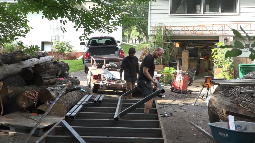
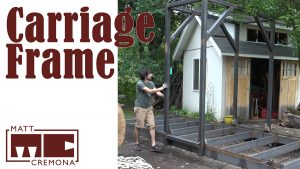
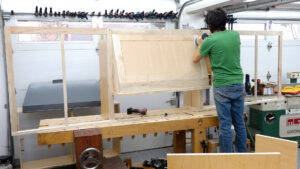
With the track built, now we need something to run on it. The carriage will hold the saw head and travel down the track. This is just the basic carriage frame. As we get into adding the saw head, many additions will be made.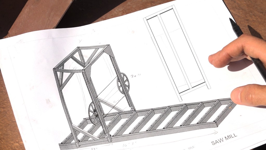
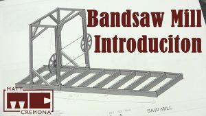
Here’s a look at the plans I shared in the intro video. I mentioned that this model was just a guide to get started and to figure out the dimensions and scale of all of the parts. The carriage design will remain mostly the same. The side assemblies will have some variance. Here I am going to add a vertical member which will guide the saw head up and down. I was given a set of linear bearings for this purpose but a tube within a tube would also work just fine here and would be much easier to implement. This guide is here to resist lateral motion and does not support any direct load. The original plan also lays out two stiffening options: either a gusset plate or braces. For ease, I’ll be adding braces.
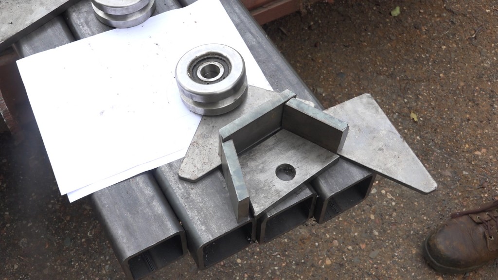
First we need to prep the uprights which means getting the wheels mounted. The wheels will be housed and supported in some fender thingies. The main component is a trapezoidal piece of 1/2″ cold rolled steel which gives the wheels enough clearance space all around. The plate has a 7/8″ hole drilled that corresponds to the 7/8″ ID of the wheel. Three sides get boxed in with some pieces cut from scrap 1/2″ steel bar.
Because I was working with scraps, the pieces that I used for the sides weren’t wide enough to provide enough space for the wheel so they are stepped back 1/4″. I actually like this look better.
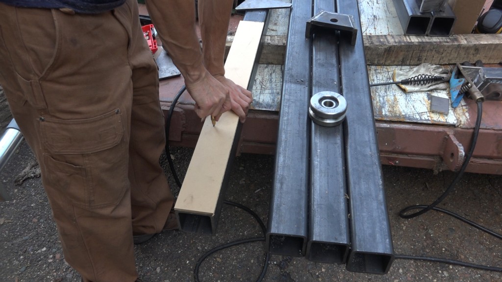
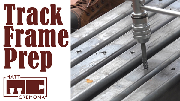
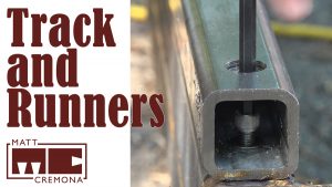
Just like I did for the runners on the track, I made a template to help located the hole location correctly across all of the uprights for the bolt that will attach the wheels.
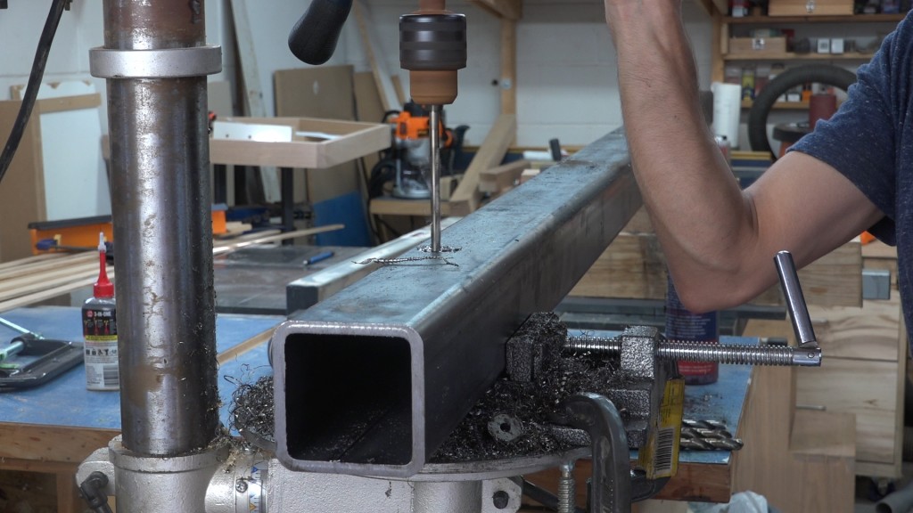
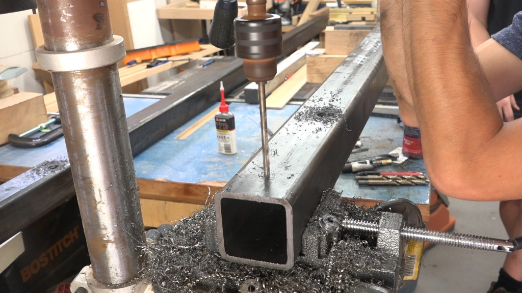
The bolt will pass through both sides of the uprights so we’ll start by drilling a 1/4″ hole through the upright
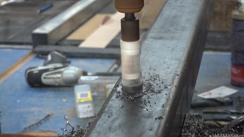
and come back with a hole saw to complete the 7/8″ hole on both sides.
While the uprights were by the drill press, I drilled a 1/4″ hole through the upright. This will allow me to run a bolt through the carriage and into the track so I can lock the carriage in position if needed.
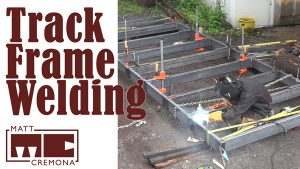
The first side assembly was laid out, tacked, and welded on top of the track frame which is nice and flat. James flipped the assembly over so I could weld the other side.
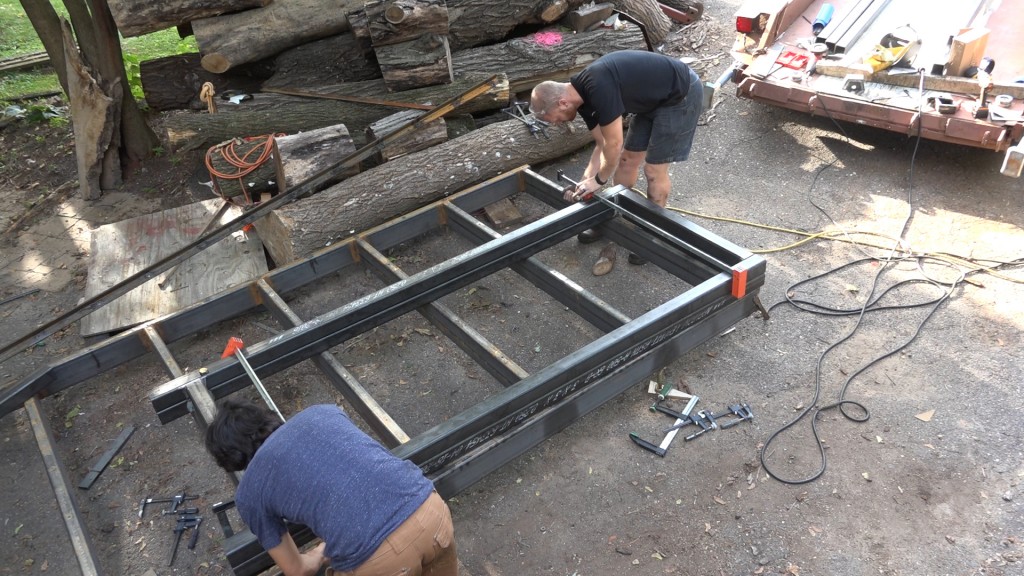
The second frame parts are laid on top of the first so we can be sure they are the same. We also installed the 7/8″ bolts to make sure those were aligned. It’s important that the wheels are aligned otherwise the frame could end up with a twist or one of the wheels might not contact the track.
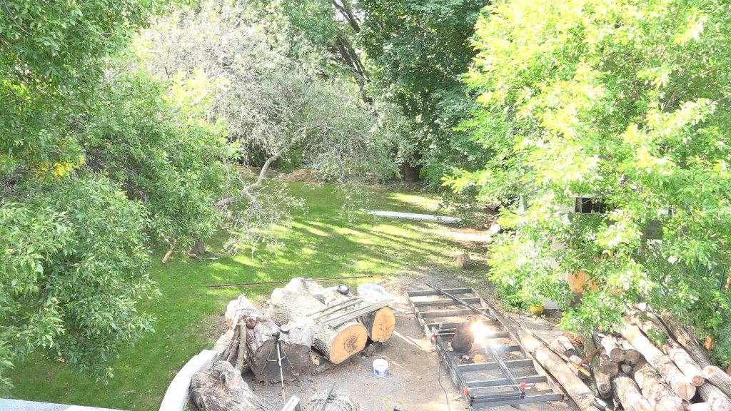
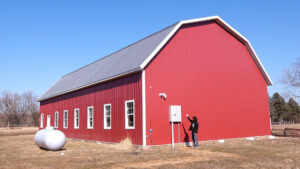
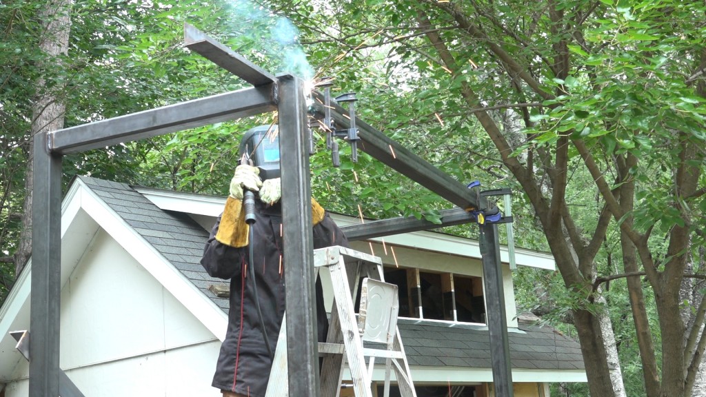
The other frame being welded. A nice shot of the backyard from the roof.
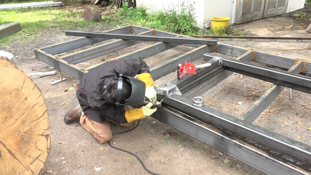
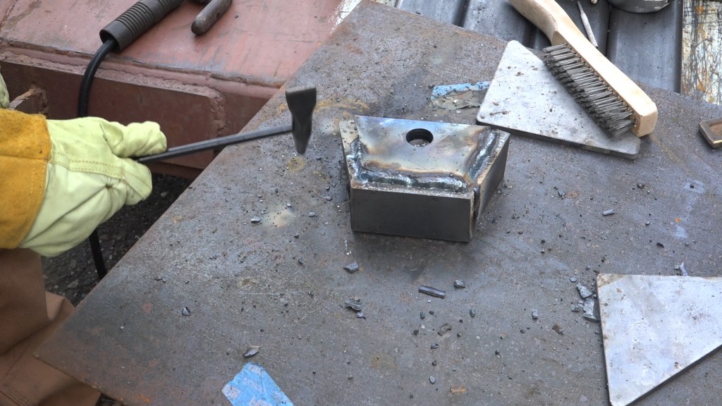
Welding on the wheel housings. These get tacked into place with the bolt and wheel installed so we know the holes are all aligned. After the housing is tacked the wheel is removed so it isn’t damaged but the bolt is left installed so the holes stay aligned if the housing distorts. I also added some gussets to the inside corners which provide for a larger attachment point for the housings. Later, I’ll come back and box in the outside of the housing and add some additional support to the top of the housing to help transfer the load back to the upright.
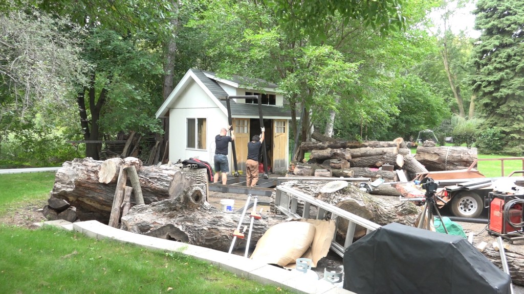
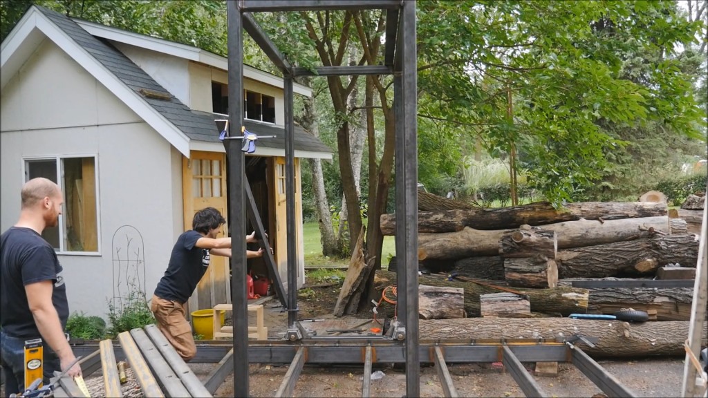
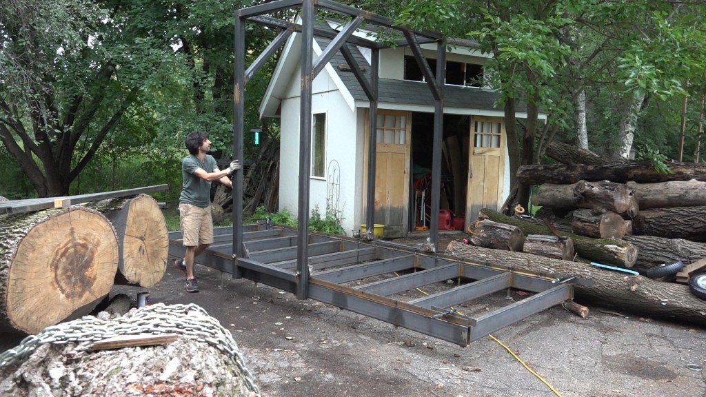
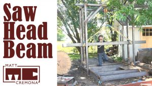
With James’s help, we stood the first assembly up onto the track and clamped some steel angles to it to brace it in place.
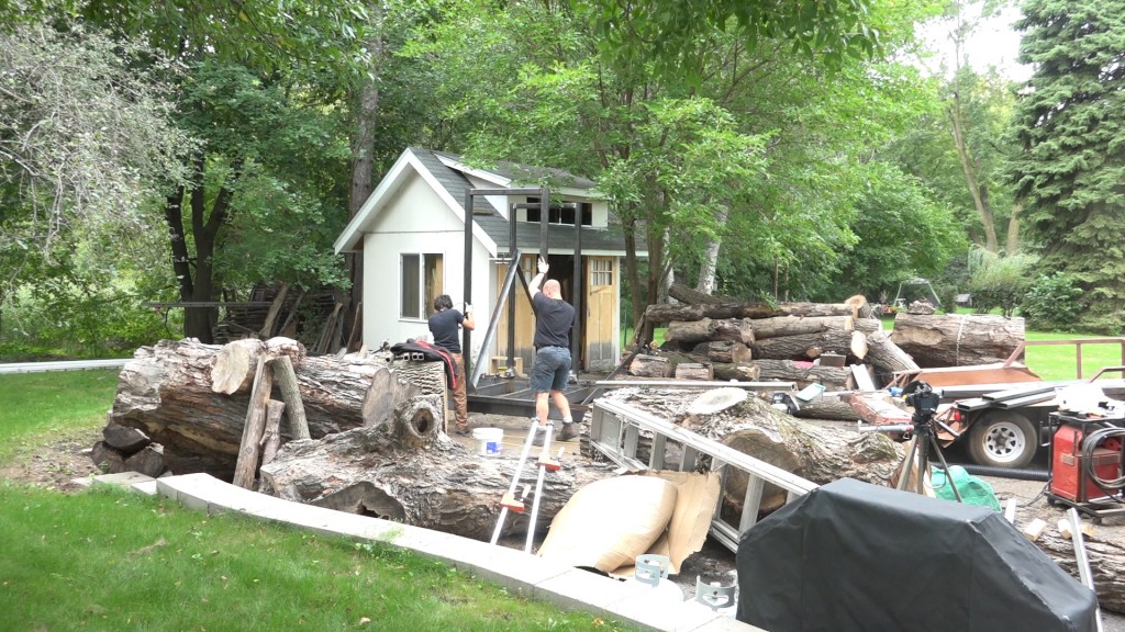
Then we could stand the second side up and clamp another angle across the top to hold it upright.
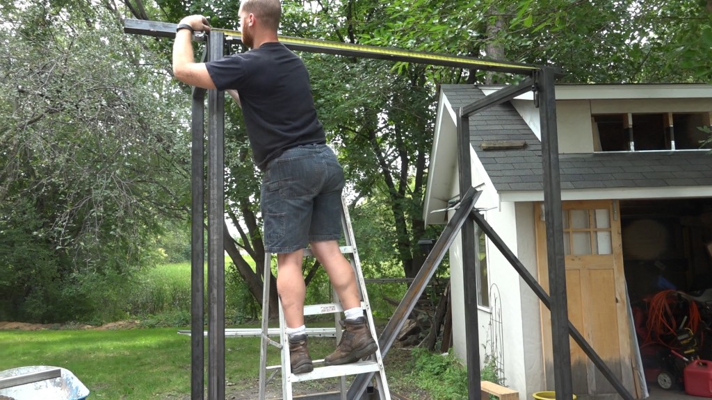
Next is the most important part: getting both sides perfectly aligned. This started by using a level to plumb the first assembly. When I made the track, I got it into level so we can know that the side assembly is perpendicular to the frame if it is plumb. Next, I ran a string from corner to corner to verify that the two sides were in the same plane (They were so our wheel holes were drilled perfectly). Next we check the base for square by measuring corner to corner. This made sure that one side wasn’t further down the track than the other. Lastly we check the top measurement to make sure it matched the bottom so we could be sure the two sides were parallel vertically.
Once everything was good, we tacked a few steel angles into place to hold everything correctly.
The top rails can be added. This got hung in place just like how I did the connecting rails on the track.
Time to give it a push – it rolles!
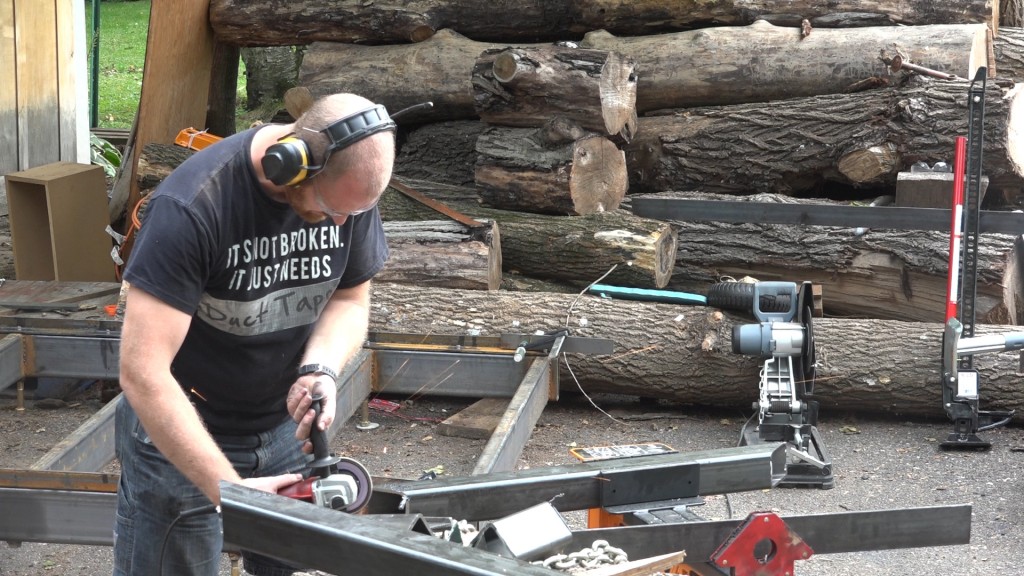
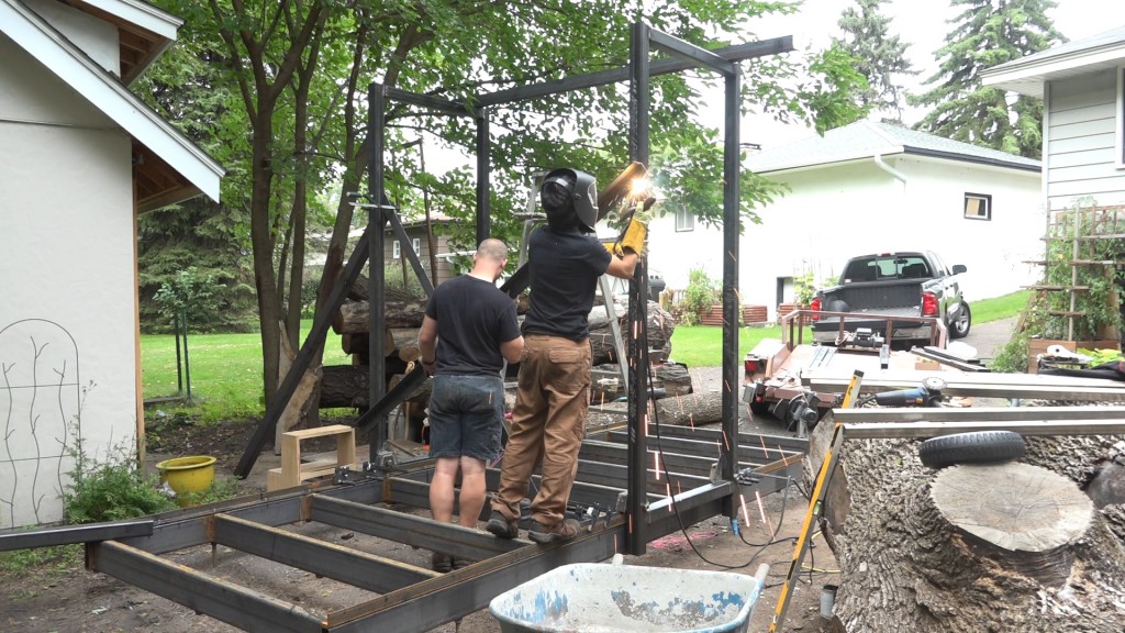
Next we can add the diagonal braces. James cut these out so some longer stock and prepped them with a grinder while I welded them in place.
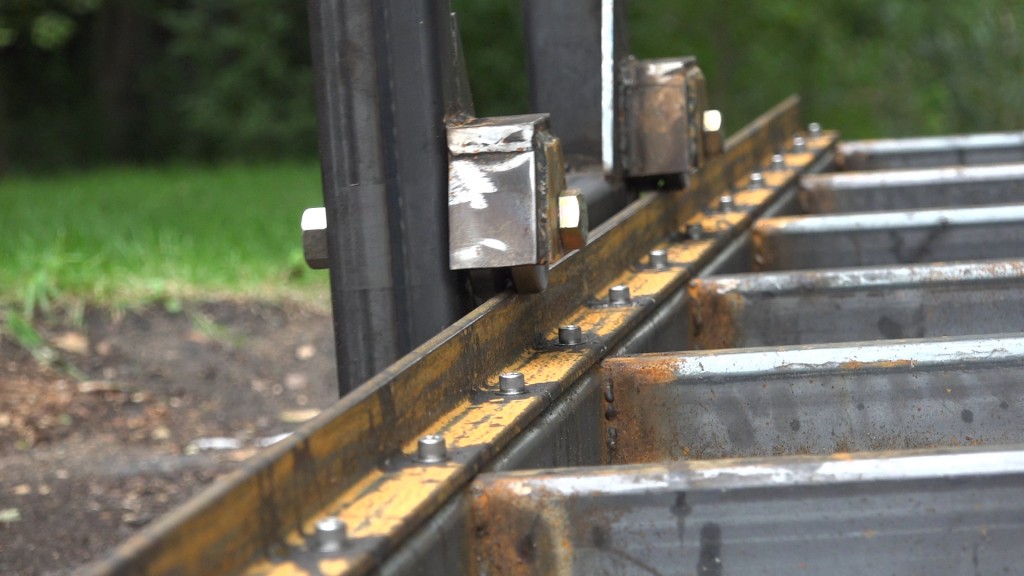
Here’s a look at the wheels riding on the track.
And an overall look at the frame.
A big thank you to James Wright from Wood by Wright for all his help. We were able to turn a pile of square tube into this carriage frame in just a day and a half!
Tap Magic Xtra Thick: http://amzn.to/2c4E0j0
Center Punch: http://amzn.to/1WIWwkN
Cobalt Drill Bit Set: http://amzn.to/2bYIRnR
7/8″ Hole Saw: http://amzn.to/2bIdU8z
Triton Super Jaws XL: http://amzn.to/2c7a8Eb
Metal Circ saw: http://amzn.to/2c3DaSS
Lincoln 225 Welder: http://amzn.to/2cvOrfU
[Amazon links are affiliate links]
Welcome to my shop! This is a quick update to let you know what I’ve been up to. This big chunky thing is the leg
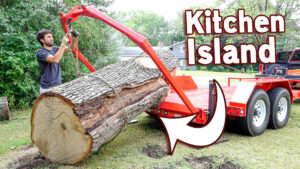
Welcome back to the home renovation. This time I’m going to be working on the kitchen island. Here is a small model of the island.
Welcome back to our home renovation. Today I am going to be working on this wall. It needs some upper cabinets and the surround for
3 Responses
Is there a reason your using a stick welder rather than say a MIG or TIG?
Stick is just what I have. Thanks!