Kitchen Island, Barn Power – March 2024 Update
Welcome to my shop! This is a quick update to let you know what I’ve been up to. This big chunky thing is the leg
This is one of those upgrades that I’ve gone back and forth on over the last few years. On one hand, I know how much nicer a spiral head can be – they’re quieter and with carbide inserts, they last a lot longer – on the other hand, I know this won’t be the last planer I’ll own which makes the cost of the upgrade a bit of a sticking point. What really pushed me to do it now was the claim that these cutter heads require more power to operate and how underpowered they can make a once powerful planer seem.
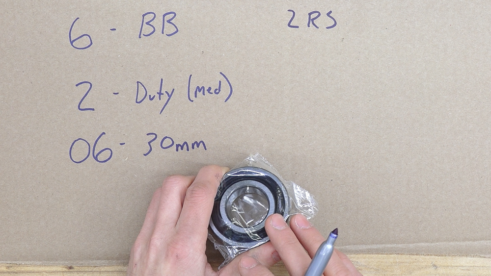
The last time I did a video that involved bearings was when I replaced the arbor bearing on my table saw. I’ve received numerous questions about sourcing replacement bearing so this time I wanted to briefly cover bearing size codes. If you know the bearing code, you can purchase the correct bearing from any supplier. One of the bearing for this cutterhead is numbered 6206 2RS. The code breaks down as follows:
6 – This first digit is the type of bearing. In this case a 6 designates a metric ball bearing (or more specifically, a single row, deep groove ball bearing). This is going to be the most common type of bearing in a woodworking machine.
2 – The second digit is the duty rating of the bearing from 0-4 with 0 being lightest and 4 being heaviest. In this case a 2 designates medium duty.
06 – The third and forth digit (if present) is the bore size. Single digits will correspond to the same number in mm. Double digits get a little more interesting. 00, 01, 02, and 03 correspond to 10, 12, 15, and 17mm. For 04 and higher, the number indicates a multiple of 5. In this case 06 designates 30mm (06 x 5mm).
2RS – The last bit of data is the seal type. Bearings can have different types of seals to keep dust and debris out or could be totally unsealed. In this case RS stands for rubber seal and 2 stands for double – both an inner and outer seal.
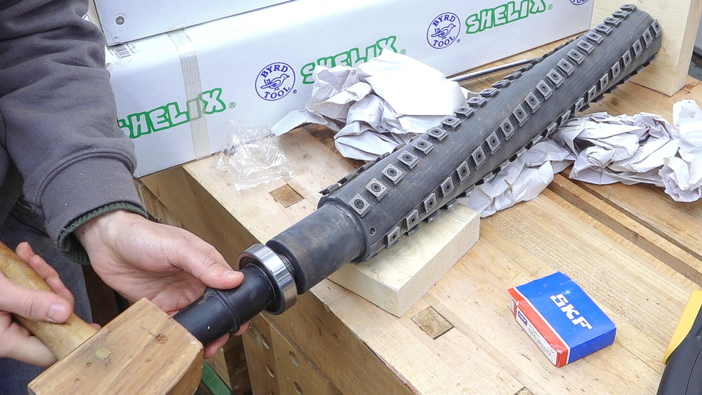
With these cutterhead upgrades, you can elect to have the bearing pressed onto the shaft from the manufactuer or you can install them yourself. I ordered my head directly from Grizzly since it was cheaper than ordering directly from Byrd so I’ll have to install them myself. This process isn’t difficult. The bearing can be tapped onto the shaft with a hammer or mallet. All you need is some sort of pipe that will slide over the shaft and only contact the inner race of the bearing. I had a plastic shop vac adapter. Usually a deep socket is a good choice but none of mine were deep enough for this operation. If you have access to a press or a machine shop with a press, its even easier.
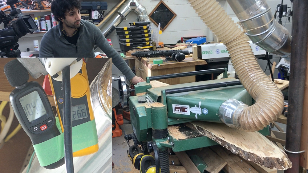
Since I’m really interested in a before and after comparison of the two cutterheads, I took a reading of the noise level and amp draw of the planer with the straight knives installed. These knives are super dull at this point and the cut depth is 3/16″ with a cut width of 10″.
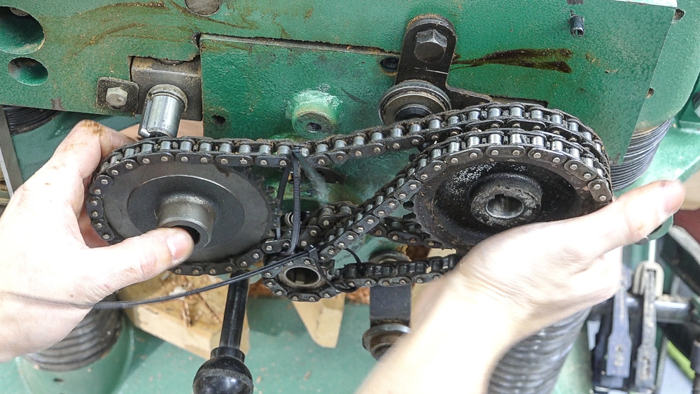
The disassembly process is pretty simple. All 4 post stationary planers are assembled the same way. These are most commonly 15″ and 20″ planers and there are already tons of guides showing the mechanical side of installing these cutterheads. I included all of the steps briefly in the video. One tip that I saw from Glen Huey is to use zip ties to hold the spockets and chains as one unit which makes sliding them on and later back on, much easier.
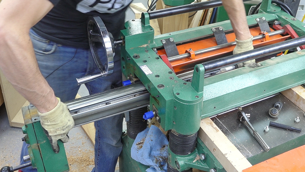
Once the planer was stripped down, the cutterhead and gearbox can be pulled as one unit. The bearing that supports the cutterhead at the side oposite of the gearbox gave me some issues as I tried to unseat it. I didn’t have anything cylindrical at the right diameter to contact the outer race, so I just used a punch to hammer it out. Since I’m not planning to reuse this bearing, I wasn’t worried about damaging it. Towards the end, I started striking the end of the shaft to fully dislodge the bearing. I set two pieces of equal thickness wood on the bed to support the cutterhead as the bearing came unseated. To remove the cutterhead, I could lower the bed a few turns and extract the cutterhead and gearbox as one unit.
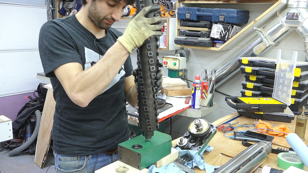
The gearbox can be opened and the old cutterhead removed by removing the gear fastened to the end of the shaft and then tapped out though the bearing and seal. The way the cutterhead, gearbox, and bearing are arranged, the cutterhead and bearing sandwich the gearbox housing between them. The bearing is installed from the inside and the cutterhead is installed from the outside. Drop the new cutterhead into the hole and use the screw that attaches the gear to pull the shaft into the bearing. I went back and forth removing the gear to check my progress. It takes a good amount of force to seat the bearing.
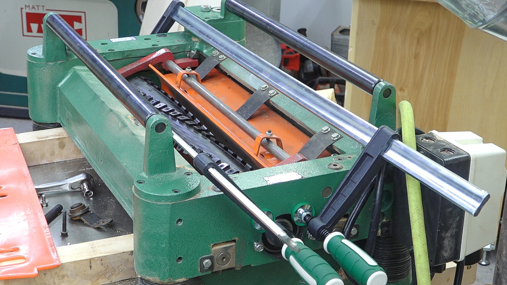
The new cutterhead and gearbox assembly can be slid into the planer. I set it on the wood and used the table to raise it until the bearing was aligned with its housing. I used a pair of clamps to seat the bearing into it’s housing. This one slid in much easier than the old one came out so I wasn’t worried about damaging the bearing pressing it in this way.
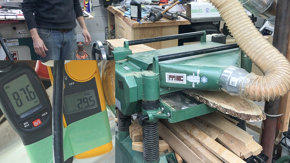
With everything reassembled, I can repeat the test. On this test, the motor came close to stalling followed by the belts slipping. The amp draw shot up to the upper 30s before I turned the machine off. I found it really interesting how much the performance differed. The planer was able to make this cut with dull straight knives but couldn’t do it with a brand new spiral head.
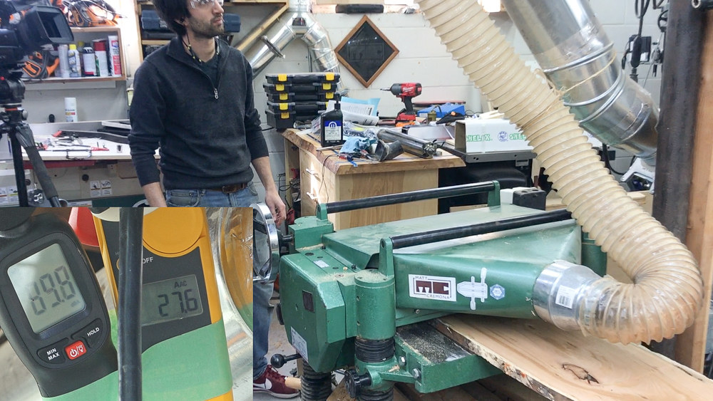
I repeated the test with a 1/8″ depth of cut and got roughly the same results as the straight knife cutterhead at 3/16″ DOC.
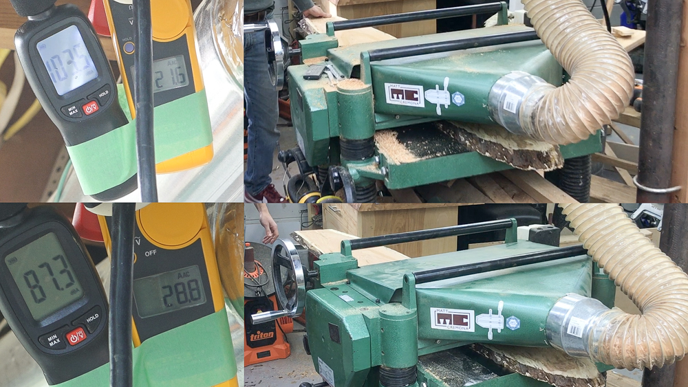
Here’s a comparison of the straight knives (top) and spiral head (bottom) at the same point on the board with a 3/16″ cut depth. There’s about a 30% increase in amps from the straight knives to the spiral knives.
It’s going to take me a little bit to get antiquated with the limits of my planer – I’ll just need to start taking lighter passes. The decrease in real world performance doesn’t seem like a huge deal. Hogging 1/8″ off a 10″ wide board is still a plenty big bite especially for anyone used to using a lunchbox style planer. I’m looking forward to not needing to worry about getting knives sharpened and swapping knives. If my experience with the inserts on my jointer are any indication, I won’t need to rotate the inserts on my planer for several years.
This planer is a Grizzly G1033 manufactured in 1996. Here are the part’s you’ll need to complete this upgrade. I’d recommend ordering the replacement gasket and seal and they will likely be damaged during disassembly. All of the hardware on this machine is metric. You’ll need metric wrenches, sockets, and hex keys.
Cutterhead: http://bit.ly/2YfW1T9
6204 Bearing: https://amzn.to/2ulBgI4
6206 Bearing: https://amzn.to/2JvGjAe
Gearbox Gasket: http://bit.ly/2FnjhpH
Gearbox Oil Seal: http://bit.ly/2FikWwL
Clamp on Amp Meter: https://amzn.to/2UOSlFZ
dB Meter: https://amzn.to/2HzuBTg
Infrared Thermometer: https://amzn.to/2UOs0YJ
Orange Gloves: https://amzn.to/2Oldvcj
Hex Wrench Set: https://amzn.to/2JwQKDp


Welcome to my shop! This is a quick update to let you know what I’ve been up to. This big chunky thing is the leg
Welcome back to the home renovation. This time I’m going to be working on the kitchen island. Here is a small model of the island.
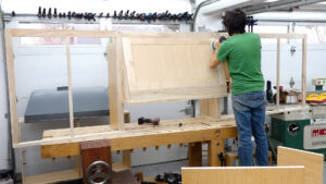
Welcome back to our home renovation. Today I am going to be working on this wall. It needs some upper cabinets and the surround for
8 Responses
Hi Matt, I have a very large maple I would love a live edge table made out of. Can you reach out to me and see if we can make something work?
Hi Shelby:
I don’t make commission pieces, so I wouldn’t be much help.
Hi Matt
I just picked up a Walker Turner Drill Press and would like to install a 3/4 HP 3 phase motor with VFD. You know a lot more about VFDs than I do so any recommendations.
Thanks
There’s a lot of options out there. I’m most familiar with the Hitachi drives since I have installed those on my sawmill and milling machine.
Hi Matt, Do you get planer snipe with the the grizzly? If so how do you deal with it and did the new head make a difference?
It’s very rare that I do. Haven’t noticed anything different with the new head in there.
It’s nice to know what I will be getting into when I do my planer. Reassembling the gearbox will be demanding. The amperage and decibel readings were good data points. Thank you for this video.
Glad it was helpful. Good luck with the upgrade!